G DC COMP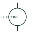
Compound-excited DC generator
A compound-excited DC generator uses documented series and shunt excitation components.
SLD / Schematic
IEEE-oriented library form of a DC generator with both series and shunt field windings, for drawing lookup.
In plain English
A compound-excited DC generator combines a shunt field across the armature with a series field carrying load current. Depending on whether the series field aids or opposes the shunt field, terminal voltage can stay nearly flat, rise or fall with load. Such machines survive in legacy battery charging, traction and test installations.
IEEE-style schematics draw the armature circle with brushes, the series field as a winding in the armature lead and the shunt field as a separate winding across the terminals. This entry is a convention-specific lookup based on a publisher's IEEE-labelled preview; the geometry here is independently drawn and is not a certified reproduction of the standard graphic.
Identify whether the shunt field is connected across the armature only (short shunt) or across the series field as well (long shunt). The vendor block identifier is a library name, not a standard number. A compound generator has both series and shunt fields; a plain DC generator symbol does not specify the field arrangement.
IEEE-oriented library form of a DC generator with both series and shunt field windings, for drawing lookup. A compound generator has both series and shunt fields; a plain DC generator symbol does not specify the field arrangement.
Read the source: Autodesk IEEE Symbol Preview — Generators · IEEE/ANSI 315-1975: graphic symbols for electrical and electronics diagrams
Autodesk publishes this block under its IEEE Symbol Preview for generators. The counterpart is the matching functional concept; no equivalence of every detailed standard graphic is asserted.
Shown as an independently authored educational illustration. Use the cited publication and drawing legend to verify the required drafting form.
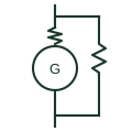
A compound-excited DC generator combines a shunt field across the armature with a series field carrying load current. Depending on whether the series field aids or opposes the shunt field, terminal voltage can stay nearly flat, rise or fall with load. Such machines survive in legacy battery charging, traction and test installations.
IEEE-style schematics draw the armature circle with brushes, the series field as a winding in the armature lead and the shunt field as a separate winding across the terminals. This entry is a convention-specific lookup based on a publisher's IEEE-labelled preview; the geometry here is independently drawn and is not a certified reproduction of the standard graphic.
A compound generator has both series and shunt fields; a plain DC generator symbol does not specify the field arrangement.
These public references support the explanation and provide further detail. Their graphics and downloadable files remain with their publishers.
Public IEEE-oriented generator category page listing the compound-excitation DC generator block.
Graphic-symbol standards context; not a source of reproduced artwork.
This illustration was authored independently by Elora Grid to explain the concept. It is not reproduced from a customer drawing, an official standard graphic or a manufacturer CAD file. Its correspondence to an exact IEC or IEEE symbol identifier has not been certified.
SVG and DXF downloads contain this original artwork. DXF uses unscaled drawing units; a GA envelope supplies no product dimensions, clearances or fabrication information. Original artwork is available under CC BY 4.0. Third-party references retain their own terms.
A compound-excited DC generator uses documented series and shunt excitation components.
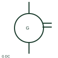
IEEE-oriented graphical reference for dc generator, with public vendor evidence and drawing-reading notes.
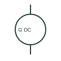
A DC generator converts mechanical input into a documented DC electrical output.
Elora Grid helps electrical teams work with drawings, specifications and equipment information. Explore the drafting workflow or join the early-access waitlist.