G DC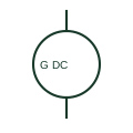
DC generator
A DC generator converts mechanical input into a documented DC electrical output.
SLD / Schematic
IEEE-oriented graphical reference for dc generator, with public vendor evidence and drawing-reading notes.
Autodesk explicitly publishes this block under IEEE Symbol Preview. The counterpart is the matching functional concept; no equivalence of every detailed standard graphic is asserted.
Shown as an independently authored educational illustration. Use the cited publication and drawing legend to verify the required drafting form.
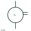
The DC generator form identifies a documented source of direct-current output. Polarity and excitation connections establish how the generated circuit supplies its load, while the mechanical prime mover is referenced separately.
This is a convention-specific lookup based on the publisher's IEEE-labelled preview. The geometry here is independently drawn to explain the connection or operation; it is not a certified reproduction of the standard graphic.
A DC source-generating function differs from a DC motor load despite related machine principles.
These public references support the explanation and provide further detail. Their graphics and downloadable files remain with their publishers.
Exact public IEEE-oriented category page verifying the component name and vendor block identifier.
Graphic-symbol standards context and official status; not a source of reproduced artwork.
This illustration was authored independently by Elora Grid to explain the concept. It is not reproduced from a customer drawing, an official standard graphic or a manufacturer CAD file. Its correspondence to an exact IEC or IEEE symbol identifier has not been certified.
SVG and DXF downloads contain this original artwork. DXF uses unscaled drawing units; a GA envelope supplies no product dimensions, clearances or fabrication information. Original artwork is available under CC BY 4.0. Third-party references retain their own terms.
A DC generator converts mechanical input into a documented DC electrical output.

An electrical generating source represented in a power-system drawing.

Checks documented synchronising conditions before a permitted connection.
Elora Grid helps electrical teams work with drawings, specifications and equipment information. Explore the drafting workflow or join the early-access waitlist.