CROSSING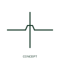
Unconnected conductor crossing
An unconnected crossing shows conductors passing across each other in the drawing without an electrical junction.
Schematic
IEEE-oriented hop or loop drawn where one conductor passes over another without connecting.
In plain English
Older ANSI-style schematics often draw a small semicircular hop where one conductor crosses another, removing any doubt that the two are unconnected. Many CAD packages offer the hop, a gap or a plain crossing as display options, and the choice is set per drawing set.
The hop carries no physical meaning; it is a reading aid. This illustration is an independent explanation of the convention rather than a reproduction of the IEEE graphic. Where a drawing set mixes hops and plain crossings, check the legend rather than assuming that plain crossings are connected.
Treat the hop as no connection. Check whether the drawing set also uses plain crossings. A hop is an unconnected crossing; a junction dot is a connection.
IEEE-oriented hop or loop drawn where one conductor passes over another without connecting. A hop is an unconnected crossing; a junction dot is a connection.
Read the source: Wire connection dots, crossing gaps and loops · IEEE/ANSI 315-1975: graphic symbols for electrical and electronics diagrams
Drawn from the publisher's wire crossing display guidance and IEEE drafting context; no equivalence of every detailed standard graphic is asserted.
Shown as an independently authored educational illustration. Use the cited publication and drawing legend to verify the required drafting form.
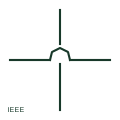
Older ANSI-style schematics often draw a small semicircular hop where one conductor crosses another, removing any doubt that the two are unconnected. Many CAD packages offer the hop, a gap or a plain crossing as display options, and the choice is set per drawing set.
The hop carries no physical meaning; it is a reading aid. This illustration is an independent explanation of the convention rather than a reproduction of the IEEE graphic. Where a drawing set mixes hops and plain crossings, check the legend rather than assuming that plain crossings are connected.
A hop is an unconnected crossing; a junction dot is a connection.
These public references support the explanation and provide further detail. Their graphics and downloadable files remain with their publishers.
Public guidance on crossing gaps and loops.
Graphic-symbol standards context and official status; not a source of reproduced artwork.
This illustration was authored independently by Elora Grid to explain the concept. It is not reproduced from a customer drawing, an official standard graphic or a manufacturer CAD file. Its correspondence to an exact IEC or IEEE symbol identifier has not been certified.
SVG and DXF downloads contain this original artwork. DXF uses unscaled drawing units; a GA envelope supplies no product dimensions, clearances or fabrication information. Original artwork is available under CC BY 4.0. Third-party references retain their own terms.
An unconnected crossing shows conductors passing across each other in the drawing without an electrical junction.
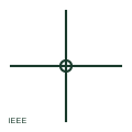
IEEE-oriented junction dot marking a connection between crossing or meeting conductors on an ANSI-style schematic.
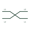
A crossing mark showing that two or more conductors swap position, such as a phase transposition or deliberate phase swap.
Elora Grid helps electrical teams work with drawings, specifications and equipment information. Explore the drafting workflow or join the early-access waitlist.