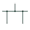
Terminal
Terminal connection
An identified electrical connection point linking schematic and wiring information.
Schematic
An unconnected crossing shows conductors passing across each other in the drawing without an electrical junction.
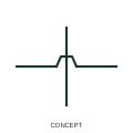
An unconnected crossing shows conductors passing across each other in the drawing without an electrical junction. The wires overlap in the two-dimensional page layout but remain distinct circuits. A gap or bridge/loop makes that distinction visible where the selected drawing convention uses one.
Check both the displayed graphic and the CAD network topology. A crossing must not acquire an unintended junction when drawing segments are moved or edited.
A gap or bridge is a drafting convention, not a physical cable crossover dimension.
These public references support the explanation and provide further detail. Their graphics and downloadable files remain with their publishers.
Official public publisher family name and reference context; vendor identifiers and graphics are distinct from licensed IEC database content.
This illustration was authored independently by Elora Grid to explain the concept. It is not reproduced from a customer drawing, an official standard graphic or a manufacturer CAD file. Its correspondence to an exact IEC or IEEE symbol identifier has not been certified.
SVG and DXF downloads contain this original artwork. DXF uses unscaled drawing units; a GA envelope supplies no product dimensions, clearances or fabrication information. Original artwork is available under CC BY 4.0. Third-party references retain their own terms.
Elora Grid helps electrical teams work with drawings, specifications and equipment information. Explore the drafting workflow or join the early-access waitlist.