DB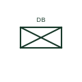
Distribution board plan mark
Plan mark showing the position of a distribution board or consumer unit on an installation layout.
IEC
US plan symbol for a panelboard, drawn as a rectangle on the wall with fill indicating flush or surface mounting.
In plain English
US plans draw panelboards as rectangles against the wall, with fill or hatching that distinguishes flush-mounted from surface-mounted cabinets. The panel name, such as LP-1A, is written beside it and matches the panel schedule and home-run labels.
The symbol helps coordinate wall depth for flush cabinets and working clearance in front of the panel. Readers should check that the space shown on the plan meets the required clear working space. The symbol does not show bus rating, main breaker or circuit count. These are in the panel schedule.
Distinguish flush and surface panels by fill. Match the label with the panel schedule. The IEC distribution board plan mark serves the same locating role under a different convention.
US plan symbol for a panelboard, drawn as a rectangle on the wall with fill indicating flush or surface mounting. The IEC distribution board plan mark serves the same locating role under a different convention.
Read the source: IEEE/ANSI 315-1975: graphic symbols for electrical and electronics diagrams
US architectural electrical plan practice in the ANSI Y32.9 lineage, read alongside IEEE 315 context; independently drawn, not a certified IEEE or ANSI graphic.
Shown as an independently authored educational illustration. Use the cited publication and drawing legend to verify the required drafting form.
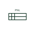
US plans draw panelboards as rectangles against the wall, with fill or hatching that distinguishes flush-mounted from surface-mounted cabinets. The panel name, such as LP-1A, is written beside it and matches the panel schedule and home-run labels.
The symbol helps coordinate wall depth for flush cabinets and working clearance in front of the panel. Readers should check that the space shown on the plan meets the required clear working space. The symbol does not show bus rating, main breaker or circuit count. These are in the panel schedule.
The IEC distribution board plan mark serves the same locating role under a different convention.
These public references support the explanation and provide further detail. Their graphics and downloadable files remain with their publishers.
Graphic-symbol standards context; not a source of reproduced artwork.
This illustration was authored independently by Elora Grid to explain the concept. It is not reproduced from a customer drawing, an official standard graphic or a manufacturer CAD file. Its correspondence to an exact IEC or IEEE symbol identifier has not been certified.
SVG and DXF downloads contain this original artwork. DXF uses unscaled drawing units; a GA envelope supplies no product dimensions, clearances or fabrication information. Original artwork is available under CC BY 4.0. Third-party references retain their own terms.
Elora Grid helps electrical teams work with drawings, specifications and equipment information. Explore the drafting workflow or join the early-access waitlist.