HIN1P25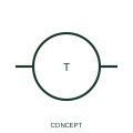
Pyrometer indication
A pyrometer indication identifies the documented temperature-measurement display function.
IEC
IEEE-library thermometer/pyrometer form for high-temperature indication, often from thermocouples or radiation sensors.
In plain English
Pyrometer indication is used where temperatures are too high for ordinary thermometers, such as furnaces, kilns and exhaust gas. The instrument is commonly fed from a thermocouple or an optical radiation sensor, so the input wiring and any cold-junction compensation must be shown with the instrument.
The form identifies the indicating instrument, not the sensing principle. A radiation pyrometer and a thermocouple pyrometer look the same at the instrument circle, and emissivity settings or sensor range limits must come from the instrument data.
Identify the sensing element feeding the pyrometer. Check for cold-junction compensation when a thermocouple is used. The pyrometer form signals a high-temperature indicator; the general thermometer form covers ordinary temperature indication.
IEEE-library thermometer/pyrometer form for high-temperature indication, often from thermocouples or radiation sensors. The pyrometer form signals a high-temperature indicator; the general thermometer form covers ordinary temperature indication.
Read the source: Autodesk IEEE Symbol Preview — Instrumentation and Sensors · IEEE/ANSI 315-1975: graphic symbols for electrical and electronics diagrams
Autodesk publishes this block under its IEEE Symbol Preview. The counterpart is the matching functional concept in the library; no equivalence of every detailed standard graphic is asserted.
Shown as an independently authored educational illustration. Use the cited publication and drawing legend to verify the required drafting form.
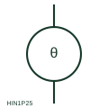
Pyrometer indication is used where temperatures are too high for ordinary thermometers, such as furnaces, kilns and exhaust gas. The instrument is commonly fed from a thermocouple or an optical radiation sensor, so the input wiring and any cold-junction compensation must be shown with the instrument.
The form identifies the indicating instrument, not the sensing principle. A radiation pyrometer and a thermocouple pyrometer look the same at the instrument circle, and emissivity settings or sensor range limits must come from the instrument data.
The pyrometer form signals a high-temperature indicator; the general thermometer form covers ordinary temperature indication.
These public references support the explanation and provide further detail. Their graphics and downloadable files remain with their publishers.
Public IEEE-oriented Instrumentation and Sensors preview listing the Thermometer/Pyrometer block and its vendor identifier.
Graphic-symbol standards context and official status; not a source of reproduced artwork.
This illustration was authored independently by Elora Grid to explain the concept. It is not reproduced from a customer drawing, an official standard graphic or a manufacturer CAD file. Its correspondence to an exact IEC or IEEE symbol identifier has not been certified.
SVG and DXF downloads contain this original artwork. DXF uses unscaled drawing units; a GA envelope supplies no product dimensions, clearances or fabrication information. Original artwork is available under CC BY 4.0. Third-party references retain their own terms.
A pyrometer indication identifies the documented temperature-measurement display function.
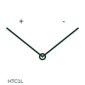
IEEE-library thermocouple form showing the junction of two dissimilar conductors and their polarity leads.
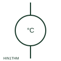
IEEE-library thermometer instrument form for a local or panel temperature reading taken from a sensor input.
Elora Grid helps electrical teams work with drawings, specifications and equipment information. Explore the drafting workflow or join the early-access waitlist.