TC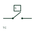
Thermocouple
A thermocouple produces a temperature-dependent voltage associated with its dissimilar-metal junction system.
Schematic
IEEE-library thermocouple form showing the junction of two dissimilar conductors and their polarity leads.
In plain English
The thermocouple form shows two dissimilar conductors meeting at a measuring junction, with the free ends wired to an instrument or device that turns a measured quantity into a signal. The library offers left and right handed versions so the junction can face the process side of the drawing, and the two leads must keep their polarity all the way to the cold junction.
The symbol does not identify the thermocouple type (for example K, J or T), the sheath or the extension cable. Those details matter because ordinary copper wiring between the head and the instrument introduces error unless matching extension or compensating cable is used.
Check the thermocouple type in the instrument schedule. Verify extension cable type and polarity from the head to the input. A thermocouple generates a small voltage from a temperature difference; an RTD changes resistance and needs an excitation current.
IEEE-library thermocouple form showing the junction of two dissimilar conductors and their polarity leads. A thermocouple generates a small voltage from a temperature difference; an RTD changes resistance and needs an excitation current.
Read the source: Autodesk IEEE Symbol Preview — Instrumentation and Sensors · IEEE/ANSI 315-1975: graphic symbols for electrical and electronics diagrams
Autodesk publishes this block under its IEEE Symbol Preview. The counterpart is the matching functional concept in the library; no equivalence of every detailed standard graphic is asserted.
Shown as an independently authored educational illustration. Use the cited publication and drawing legend to verify the required drafting form.

The thermocouple form shows two dissimilar conductors meeting at a measuring junction, with the free ends wired to an instrument or transducer. The library offers left and right handed versions so the junction can face the process side of the drawing, and the two leads must keep their polarity all the way to the cold junction.
The symbol does not identify the thermocouple type (for example K, J or T), the sheath or the extension cable. Those details matter because ordinary copper wiring between the head and the instrument introduces error unless matching extension or compensating cable is used.
A thermocouple generates a small voltage from a temperature difference; an RTD changes resistance and needs an excitation current.
These public references support the explanation and provide further detail. Their graphics and downloadable files remain with their publishers.
Public IEEE-oriented Instrumentation and Sensors preview listing the Thermocouple block and its vendor identifier.
Graphic-symbol standards context and official status; not a source of reproduced artwork.
This illustration was authored independently by Elora Grid to explain the concept. It is not reproduced from a customer drawing, an official standard graphic or a manufacturer CAD file. Its correspondence to an exact IEC or IEEE symbol identifier has not been certified.
SVG and DXF downloads contain this original artwork. DXF uses unscaled drawing units; a GA envelope supplies no product dimensions, clearances or fabrication information. Original artwork is available under CC BY 4.0. Third-party references retain their own terms.
A thermocouple produces a temperature-dependent voltage associated with its dissimilar-metal junction system.
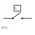
An RTD is a temperature sensor whose resistance changes with temperature.
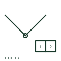
IEEE-library thermocouple form that adds the head terminal board where element leads change to field cable.
Elora Grid helps electrical teams work with drawings, specifications and equipment information. Explore the drafting workflow or join the early-access waitlist.