HCN1RSGL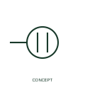
Single power receptacle
This form identifies a single power receptacle connection in the publisher's installation family.
IEC
US-style plan symbol for a single convenience receptacle: a circle with one line through it on the wall.
In plain English
In US architectural electrical plans a single receptacle is commonly drawn as a small circle on the wall line with a single line through it. The form is quick to draw and visually lighter than the IEC half circle, and it is placed with the circle against the wall where the device box is installed.
Single receptacles are typically dedicated outlets for an appliance such as a refrigerator or a piece of equipment that must not share the outlet. Mounting height, NEMA configuration and circuit number are written beside the symbol or in a note.
The symbol does not tell you the NEMA configuration or whether the outlet is tamper-resistant. The receptacle schedule and code notes provide those details.
US-style plan symbol for a single convenience receptacle: a circle with one line through it on the wall. The ANSI duplex receptacle uses two lines through the circle; the single form uses one.
Read the source: IEEE/ANSI 315-1975: graphic symbols for electrical and electronics diagrams · Autodesk IEC-60617 preview: Single and duplex power-receptacle forms
US architectural electrical plan practice in the ANSI Y32.9 lineage, read alongside IEEE 315 context; independently drawn, not a certified IEEE or ANSI graphic.
Shown as an independently authored educational illustration. Use the cited publication and drawing legend to verify the required drafting form.

In US architectural electrical plans a single receptacle is commonly drawn as a small circle on the wall line with a single line through it. The form is quick to draw and visually lighter than the IEC half circle, and it is placed with the circle against the wall where the device box is installed.
Single receptacles are typically dedicated outlets for an appliance such as a refrigerator or a piece of equipment that must not share the outlet. Mounting height, NEMA configuration and circuit number are written beside the symbol or in a note.
The symbol does not tell you the NEMA configuration or whether the outlet is tamper-resistant. The receptacle schedule and code notes provide those details.
The ANSI duplex receptacle uses two lines through the circle; the single form uses one.
These public references support the explanation and provide further detail. Their graphics and downloadable files remain with their publishers.
Graphic-symbol standards context and official status; not a source of reproduced artwork.
Public receptacle family in an IEC-oriented CAD library, useful for comparing schematic receptacle forms with plan marks.
This illustration was authored independently by Elora Grid to explain the concept. It is not reproduced from a customer drawing, an official standard graphic or a manufacturer CAD file. Its correspondence to an exact IEC or IEEE symbol identifier has not been certified.
SVG and DXF downloads contain this original artwork. DXF uses unscaled drawing units; a GA envelope supplies no product dimensions, clearances or fabrication information. Original artwork is available under CC BY 4.0. Third-party references retain their own terms.
This form identifies a single power receptacle connection in the publisher's installation family.
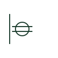
US-style plan symbol for the standard duplex receptacle: a wall-mounted circle crossed by two parallel lines.
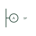
US plan symbol for a special-purpose outlet or connection serving a specific appliance, keyed to a schedule.
Elora Grid helps electrical teams work with drawings, specifications and equipment information. Explore the drafting workflow or join the early-access waitlist.