SPARK GAP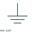
Spark-gap protective element
A spark-gap element provides a documented breakdown path across separated electrodes.
SLD / Schematic
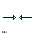
IEEE-oriented spark gap drawn as two facing electrodes separated by an air gap, which breaks down at high voltage.
In plain English
A spark gap is a pair of electrodes separated by a gap that flashes over when the voltage exceeds its breakdown level. It appears in surge protection of telecom and control circuits and on older equipment as coordinating gaps. The publisher's IEEE miscellaneous preview lists a spark gap form, the counterpart of the existing IEC page.
This illustration is independent and not the IEEE graphic. A plain spark gap can sustain follow current after breakdown on power circuits, which is why power arresters use other technology. The breakdown voltage depends on gap spacing and conditions, and must be specified.
Check whether follow current could be sustained on the circuit. Read breakdown voltage from equipment data. A spark gap is a simple breakdown element; a gas discharge tube encloses the gap in gas for a defined breakdown.
IEEE-oriented spark gap drawn as two facing electrodes separated by an air gap, which breaks down at high voltage. A spark gap is a simple breakdown element; a gas discharge tube encloses the gap in gas for a defined breakdown.
Read the source: Autodesk IEEE Symbol Preview — Miscellaneous · IEEE/ANSI 315-1975: graphic symbols for electrical and electronics diagrams
Autodesk publishes this block under IEEE Symbol Preview: Miscellaneous. The counterpart is the matching functional concept; no equivalence of every detailed standard graphic is asserted.
Shown as an independently authored educational illustration. Use the cited publication and drawing legend to verify the required drafting form.
A spark gap is a pair of electrodes separated by a gap that flashes over when the voltage exceeds its breakdown level. It appears in surge protection of telecom and control circuits and on older equipment as coordinating gaps. The publisher's IEEE miscellaneous preview lists a spark gap form, the counterpart of the existing IEC page.
This illustration is independent and not the IEEE graphic. A plain spark gap can sustain follow current after breakdown on power circuits, which is why power arresters use other technology. The breakdown voltage depends on gap spacing and conditions, and must be specified.
A spark gap is a simple breakdown element; a gas discharge tube encloses the gap in gas for a defined breakdown.
These public references support the explanation and provide further detail. Their graphics and downloadable files remain with their publishers.
Exact public IEEE-oriented category page listing the spark gap form.
Graphic-symbol standards context and official status; not a source of reproduced artwork.
This illustration was authored independently by Elora Grid to explain the concept. It is not reproduced from a customer drawing, an official standard graphic or a manufacturer CAD file. Its correspondence to an exact IEC or IEEE symbol identifier has not been certified.
SVG and DXF downloads contain this original artwork. DXF uses unscaled drawing units; a GA envelope supplies no product dimensions, clearances or fabrication information. Original artwork is available under CC BY 4.0. Third-party references retain their own terms.
A spark-gap element provides a documented breakdown path across separated electrodes.
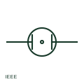
IEEE-oriented protective gas discharge tube: electrodes within a sealed envelope that conduct when voltage exceeds breakdown.
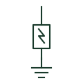
IEEE-oriented surge arrester symbol connected between a line and ground to limit transient overvoltage.
Elora Grid helps electrical teams work with drawings, specifications and equipment information. Explore the drafting workflow or join the early-access waitlist.