PE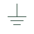
Protective earth
An identified connection serving the protective earthing function.
SLD / Schematic
A spark-gap element provides a documented breakdown path across separated electrodes.
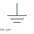
A spark-gap element provides a documented breakdown path across separated electrodes. Its drawing identifies the protective location without implying the same behaviour as a semiconductor clamp.
A spark-gap element and a varistor use different protective mechanisms.
These public references support the explanation and provide further detail. Their graphics and downloadable files remain with their publishers.
Public documentation of this equipment function or named vendor variant; the illustration is independently authored and is not the source graphic.
This illustration was authored independently by Elora Grid to explain the concept. It is not reproduced from a customer drawing, an official standard graphic or a manufacturer CAD file. Its correspondence to an exact IEC or IEEE symbol identifier has not been certified.
SVG and DXF downloads contain this original artwork. DXF uses unscaled drawing units; a GA envelope supplies no product dimensions, clearances or fabrication information. Original artwork is available under CC BY 4.0. Third-party references retain their own terms.
Elora Grid helps electrical teams work with drawings, specifications and equipment information. Explore the drafting workflow or join the early-access waitlist.