HTC1LTB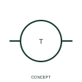
Thermocouple with terminal board
This representation distinguishes a thermocouple circuit expanded to show its terminal-board interface.
IEC
IEEE-library thermocouple form that adds the head terminal board where element leads change to field cable.
In plain English
This form adds the terminal board in the thermocouple head to the basic junction symbol. It is useful on loop and wiring diagrams because the terminal board marks the boundary between the element, which is replaced with the sensor, and the field extension cable, which stays in place.
Drawing the terminal board makes polarity at the changeover explicit, but it still does not tell you the thermocouple type or whether the head contains a transmitter. If a head-mounted transmitter is fitted, the output becomes a current loop and should be drawn as such.
Use the terminal numbers to check polarity at the head. Confirm whether a head transmitter replaces the direct millivolt connection. The terminal-board form shows the head connection point; the plain thermocouple form shows only the junction and leads.
IEEE-library thermocouple form that adds the head terminal board where element leads change to field cable. The terminal-board form shows the head connection point; the plain thermocouple form shows only the junction and leads.
Read the source: Autodesk IEEE Symbol Preview — Instrumentation and Sensors · IEEE/ANSI 315-1975: graphic symbols for electrical and electronics diagrams
Autodesk publishes this block under its IEEE Symbol Preview. The counterpart is the matching functional concept in the library; no equivalence of every detailed standard graphic is asserted.
Shown as an independently authored educational illustration. Use the cited publication and drawing legend to verify the required drafting form.
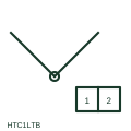
This form adds the terminal board in the thermocouple head to the basic junction symbol. It is useful on loop and wiring diagrams because the terminal board marks the boundary between the element, which is replaced with the sensor, and the field extension cable, which stays in place.
Drawing the terminal board makes polarity at the changeover explicit, but it still does not tell you the thermocouple type or whether the head contains a transmitter. If a head-mounted transmitter is fitted, the output becomes a current loop and should be drawn as such.
The terminal-board form shows the head connection point; the plain thermocouple form shows only the junction and leads.
These public references support the explanation and provide further detail. Their graphics and downloadable files remain with their publishers.
Public IEEE-oriented Instrumentation and Sensors preview listing the Thermocouple with Terminal Board block and its vendor identifier.
Graphic-symbol standards context and official status; not a source of reproduced artwork.
This illustration was authored independently by Elora Grid to explain the concept. It is not reproduced from a customer drawing, an official standard graphic or a manufacturer CAD file. Its correspondence to an exact IEC or IEEE symbol identifier has not been certified.
SVG and DXF downloads contain this original artwork. DXF uses unscaled drawing units; a GA envelope supplies no product dimensions, clearances or fabrication information. Original artwork is available under CC BY 4.0. Third-party references retain their own terms.
This representation distinguishes a thermocouple circuit expanded to show its terminal-board interface.
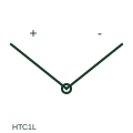
IEEE-library thermocouple form showing the junction of two dissimilar conductors and their polarity leads.
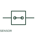
A sensor terminal organises supply, return and signal connections for a documented sensor wiring arrangement.
Elora Grid helps electrical teams work with drawings, specifications and equipment information. Explore the drafting workflow or join the early-access waitlist.