BS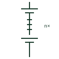
Battery string
A series connection of cells or modules reaching the system DC voltage, often with its own fuse or breaker and monitoring.
SLD / Schematic
A rack of series-connected battery modules with its own switchgear and battery management unit, forming one DC source.
In plain English
In stationary lithium-ion systems a battery rack holds modules connected in series to form one string, together with a rack-level switchgear box containing contactors, fuses, precharge circuit and the rack battery management unit. Racks are then paralleled onto a DC bus feeding the power conversion system.
Single-line diagrams draw each rack as a battery symbol within a boundary box that also contains the rack contactors and fuse, with the management unit shown as a small block linked by a communication line. Large systems may show one typical rack and note the number of racks in parallel.
The rack boundary on an electrical drawing does not describe mechanical arrangement, fire separation or cooling. It also does not state whether racks of different capacities can be mixed, which the battery manufacturer must confirm.
A rack of series-connected battery modules with its own switchgear and battery management unit, forming one DC source. A rack is the packaged string with switchgear and management; a plain battery string symbol shows only the series cells.
Read the source: xStorage battery energy storage system · Lynx Smart BMS NG official product and documents
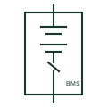
In stationary lithium-ion systems a battery rack holds modules connected in series to form one string, together with a rack-level switchgear box containing contactors, fuses, precharge circuit and the rack battery management unit. Racks are then paralleled onto a DC bus feeding the power conversion system.
Single-line diagrams draw each rack as a battery symbol within a boundary box that also contains the rack contactors and fuse, with the management unit shown as a small block linked by a communication line. Large systems may show one typical rack and note the number of racks in parallel.
The rack boundary on an electrical drawing does not describe mechanical arrangement, fire separation or cooling. It also does not state whether racks of different capacities can be mixed, which the battery manufacturer must confirm.
A rack is the packaged string with switchgear and management; a plain battery string symbol shows only the series cells.
These public references support the explanation and provide further detail. Their graphics and downloadable files remain with their publishers.
Public battery energy storage cabinet context.
Public battery management and contactor control documentation context.
This illustration was authored independently by Elora Grid to explain the concept. It is not reproduced from a customer drawing, an official standard graphic or a manufacturer CAD file. Its correspondence to an exact IEC or IEEE symbol identifier has not been certified.
SVG and DXF downloads contain this original artwork. DXF uses unscaled drawing units; a GA envelope supplies no product dimensions, clearances or fabrication information. Original artwork is available under CC BY 4.0. Third-party references retain their own terms.
A series connection of cells or modules reaching the system DC voltage, often with its own fuse or breaker and monitoring.
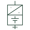
A complete battery plant block combining batteries, power conversion and controls, shown as one source or sink on an SLD.
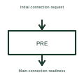
A precharge circuit limits the initial current used to charge downstream capacitance before a main connection closes.

A generic storage-equipment envelope linked to the selected battery system.
Elora Grid helps electrical teams work with drawings, specifications and equipment information. Explore the drafting workflow or join the early-access waitlist.