CT
Current transformer
A current-measurement transformer used with metering and protection equipment.
SLD / Schematic
Single unit housing a current transformer and voltage transformer for each phase, typical of MV and HV metering points.
In plain English
A combined instrument transformer places a CT and a VT in one insulated housing for each phase. It saves space and foundations at outdoor higher-voltage metering points and appears in MV metering units where the supply authority needs both current and voltage for a billing meter.
On a single-line diagram the CT and VT symbols are drawn together with a boundary showing they share one housing. The boundary does not change ratios or classes, which are still stated separately for the current and voltage parts.
Read the CT and VT ratings separately. Check sealing and access requirements for revenue metering. A combined instrument transformer houses a CT and VT together; separate units are drawn and specified independently.
Single unit housing a current transformer and voltage transformer for each phase, typical of MV and higher-voltage metering points. A combined instrument transformer houses a CT and VT together; separate units are drawn and specified independently.
Read the source: Indoor current and voltage transformers · CPB capacitor voltage transformer
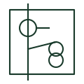
A combined instrument transformer places a CT and a VT in one insulated housing for each phase. It saves space and foundations at outdoor HV metering points and appears in MV metering units where the supply authority needs both current and voltage for a billing meter.
On a single-line diagram the CT and VT symbols are drawn together with a boundary showing they share one housing. The boundary does not change ratios or classes, which are still stated separately for the current and voltage parts.
A combined instrument transformer houses a CT and VT together; separate units are drawn and specified independently.
These public references support the explanation and provide further detail. Their graphics and downloadable files remain with their publishers.
Public manufacturer overview of indoor current and voltage instrument transformers.
Public instrument transformer product family context.
This illustration was authored independently by Elora Grid to explain the concept. It is not reproduced from a customer drawing, an official standard graphic or a manufacturer CAD file. Its correspondence to an exact IEC or IEEE symbol identifier has not been certified.
SVG and DXF downloads contain this original artwork. DXF uses unscaled drawing units; a GA envelope supplies no product dimensions, clearances or fabrication information. Original artwork is available under CC BY 4.0. Third-party references retain their own terms.
A current-measurement transformer used with metering and protection equipment.

A transformer providing a voltage signal for metering or protection.

CT with a primary winding of several turns, used for low primary currents where a bar primary gives too little accuracy.
Elora Grid helps electrical teams work with drawings, specifications and equipment information. Explore the drafting workflow or join the early-access waitlist.