3~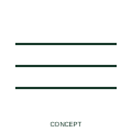
Three-phase conductor group
A conductor group represents the documented phase conductors of a circuit shown individually.
SLD / Schematic
A single oblique stroke across a line with a number beside it, stating how many conductors the single line represents.
In plain English
Where a single line stands for several conductors, the count can be shown by one oblique stroke plus a numeral rather than by repeating strokes. This is the practical form for larger counts, such as a 12 core control cable or a 4 conductor feeder, where drawing many strokes would be cluttered.
The numeral counts conductors, not circuits or phases. A value of 4 might be three phases and neutral, or four control cores, and the drawing must say which. It also does not state conductor size. On plan drawings the count is often combined with a size, for example 4 x 16 mm2, which belongs in the annotation rather than the stroke.
Confirm what conductors are included in the count, for example phases, neutral and PE. Read the size annotation separately from the count. A numeral count gives any number of conductors on one stroke; the three-phase conductor group uses three strokes specifically for three conductors.
A single oblique stroke across a line with a number beside it, stating how many conductors the single line represents. A numeral count gives any number of conductors on one stroke; the three-phase conductor group uses three strokes specifically for three conductors.
Read the source: IEC-60617 symbol preview directory · IEEE/ANSI 315-1975: graphic symbols for electrical and electronics diagrams
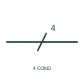
Where a single line stands for several conductors, the count can be shown by one oblique stroke plus a numeral rather than by repeating strokes. This is the practical form for larger counts, such as a 12 core control cable or a 4 conductor feeder, where drawing many strokes would be cluttered.
The numeral counts conductors, not circuits or phases. A value of 4 might be three phases and neutral, or four control cores, and the drawing must say which. It also does not state conductor size. On plan drawings the count is often combined with a size, for example 4 x 16 mm2, which belongs in the annotation rather than the stroke.
A numeral count gives any number of conductors on one stroke; the three-phase conductor group uses three strokes specifically for three conductors.
These public references support the explanation and provide further detail. Their graphics and downloadable files remain with their publishers.
Public directory of IEC-oriented symbol families.
Standards context for conductor-count conventions in IEEE graphics.
This illustration was authored independently by Elora Grid to explain the concept. It is not reproduced from a customer drawing, an official standard graphic or a manufacturer CAD file. Its correspondence to an exact IEC or IEEE symbol identifier has not been certified.
SVG and DXF downloads contain this original artwork. DXF uses unscaled drawing units; a GA envelope supplies no product dimensions, clearances or fabrication information. Original artwork is available under CC BY 4.0. Third-party references retain their own terms.
A conductor group represents the documented phase conductors of a circuit shown individually.
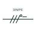
A single-line notation such as 3/N/PE showing a three-phase circuit carrying both a neutral and a separate protective conductor.
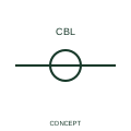
A one-line cable marker identifies the cable represented by a simplified connection line.
Elora Grid helps electrical teams work with drawings, specifications and equipment information. Explore the drafting workflow or join the early-access waitlist.