TS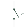
Potential test switch
Panel test switch that opens a VT secondary circuit to a relay or meter so test voltages can be applied safely.
Schematic
Panel test switch for CT circuits that shorts the CT side before opening the relay side, with a test jack between.
In plain English
Panel-mounted test switches used in North American practice often combine a knife switch with a shorting contact for each CT circuit. Opening the switch first shorts the CT secondary and then isolates the relay or meter, so a test set can be connected without exposing the CT to an open circuit.
Current test switches are usually grouped with potential test switches and trip-isolating switches on one assembly. The symbol shows a single pole, and the full assembly arrangement, including which poles are current and which are potential, must be read from the panel wiring diagram.
Confirm the shorting contact is on the CT side. Read the switch sequence for the assembly. A current test switch shorts the CT on opening; a potential test switch simply opens the voltage circuit.
Panel test switch for CT circuits that shorts the CT side before opening the relay side, with a test jack between. A current test switch shorts the CT on opening; a potential test switch simply opens the voltage circuit.
Read the source: Transformer terminals for measuring and test circuits · IEEE/ANSI 315-1975: graphic symbols for electrical and electronics diagrams
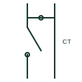
Panel-mounted test switches used in North American practice often combine a knife switch with a shorting contact for each CT circuit. Opening the switch first shorts the CT secondary and then isolates the relay or meter, so a test set can be connected without exposing the CT to an open circuit.
Current test switches are usually grouped with potential test switches and trip-isolating switches on one assembly. The symbol shows a single pole, and the full assembly arrangement, including which poles are current and which are potential, must be read from the panel wiring diagram.
A current test switch shorts the CT on opening; a potential test switch simply opens the voltage circuit.
These public references support the explanation and provide further detail. Their graphics and downloadable files remain with their publishers.
Public manufacturer range of transformer and test terminals for measuring and protection circuits.
IEEE graphic-symbol standards context; no standard glyph is reproduced.
This illustration was authored independently by Elora Grid to explain the concept. It is not reproduced from a customer drawing, an official standard graphic or a manufacturer CAD file. Its correspondence to an exact IEC or IEEE symbol identifier has not been certified.
SVG and DXF downloads contain this original artwork. DXF uses unscaled drawing units; a GA envelope supplies no product dimensions, clearances or fabrication information. Original artwork is available under CC BY 4.0. Third-party references retain their own terms.
Panel test switch that opens a VT secondary circuit to a relay or meter so test voltages can be applied safely.
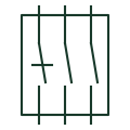
Multi-pole test facility between CT, VT and trip wiring and a relay, allowing safe isolation and test injection.
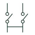
A current-transformer terminal arrangement providing documented test and shorting facilities.
Elora Grid helps electrical teams work with drawings, specifications and equipment information. Explore the drafting workflow or join the early-access waitlist.