CAP 3PH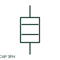
Three-phase power-factor capacitor
A three-phase capacitor assembly provides a documented reactive-power function connected to the power circuit.
SLD / Schematic
Power factor correction capacitors with series reactors that tune each step below the lowest significant harmonic.
In plain English
A detuned capacitor bank places a reactor in series with each capacitor step so that the step resonates at a frequency below the lowest significant harmonic, commonly expressed as a detuning factor such as 7 per cent, which tunes near 189 Hz on a 50 Hz network. This prevents the bank from forming a parallel resonance that would amplify 5th harmonic currents from converters.
Single-line diagrams show several capacitor steps, each with a series reactor and a switching contactor or thyristor switch, controlled by a power factor regulator using a current transformer on the incoming supply. The detuning factor is noted on the bank.
The series reactor raises the voltage across the capacitors above network voltage, so the capacitors must be rated accordingly. The symbol does not show that voltage rise, the reactor thermal rating or the regulator settings.
Power factor correction capacitors with series reactors that tune each step below the lowest significant harmonic. A detuned bank avoids resonance and absorbs little harmonic current; a tuned filter is designed to sink harmonic current.
Read the source: Capacitor and filter product offerings · Capacitive component symbols
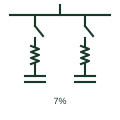
A detuned capacitor bank places a reactor in series with each capacitor step so that the step resonates at a frequency below the lowest significant harmonic, commonly expressed as a detuning factor such as 7 per cent, which tunes near 189 Hz on a 50 Hz network. This prevents the bank from forming a parallel resonance that would amplify 5th harmonic currents from converters.
Single-line diagrams show several capacitor steps, each with a series reactor and a switching contactor or thyristor switch, controlled by a power factor regulator using a current transformer on the incoming supply. The detuning factor is noted on the bank.
The series reactor raises the voltage across the capacitors above network voltage, so the capacitors must be rated accordingly. The symbol does not show that voltage rise, the reactor thermal rating or the regulator settings.
A detuned bank avoids resonance and absorbs little harmonic current; a tuned filter is designed to sink harmonic current.
These public references support the explanation and provide further detail. Their graphics and downloadable files remain with their publishers.
Public shunt compensation banks with and without reactors context.
Public capacitor symbol family context.
This illustration was authored independently by Elora Grid to explain the concept. It is not reproduced from a customer drawing, an official standard graphic or a manufacturer CAD file. Its correspondence to an exact IEC or IEEE symbol identifier has not been certified.
SVG and DXF downloads contain this original artwork. DXF uses unscaled drawing units; a GA envelope supplies no product dimensions, clearances or fabrication information. Original artwork is available under CC BY 4.0. Third-party references retain their own terms.
A three-phase capacitor assembly provides a documented reactive-power function connected to the power circuit.
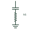
A shunt series-LC branch tuned near one harmonic order to sink that harmonic current from the network.
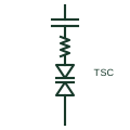
A capacitor bank switched in or out at current zero by anti-parallel thyristors, giving fast stepwise reactive support.
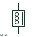
An iron-core reactor uses a documented magnetic core to provide its inductive characteristic.
Elora Grid helps electrical teams work with drawings, specifications and equipment information. Explore the drafting workflow or join the early-access waitlist.