SVC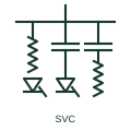
Static var compensator
A shunt reactive power compensator built from thyristor-controlled reactors, thyristor-switched capacitors and filters.
SLD
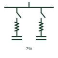
A capacitor bank switched in or out at current zero by anti-parallel thyristors, giving fast stepwise reactive support.
In plain English
A thyristor-switched capacitor connects a capacitor bank through anti-parallel thyristors, usually with a small series reactor to limit inrush. The thyristors switch the capacitor in at the instant when the network voltage equals the capacitor voltage, avoiding transients, and switch it out at current zero. It is either fully on or fully off.
Single-line diagrams show a capacitor, a series reactor and the thyristor pair stacked on a shunt branch. Several TSC branches may be drawn to give multiple steps of capacitive output in a static var compensator or a fast power factor correction system.
Because it switches in discrete steps, fine control comes from combining TSC branches with a TCR. The symbol does not show discharge resistors or the valve voltage rating, which must withstand twice the peak voltage when the capacitor is charged and the network reverses.
A capacitor bank switched in or out at current zero by anti-parallel thyristors, giving fast stepwise reactive support. A TSC switches capacitors in steps without transients; a mechanically switched capacitor uses a breaker and is much slower.
Read the source: Static Var Compensators (SVC) · Capacitive component symbols
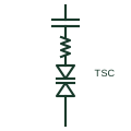
A thyristor-switched capacitor connects a capacitor bank through anti-parallel thyristors, usually with a small series reactor to limit inrush. The thyristors switch the capacitor in at the instant when the network voltage equals the capacitor voltage, avoiding transients, and switch it out at current zero. It is either fully on or fully off.
Single-line diagrams show a capacitor, a series reactor and the thyristor pair stacked on a shunt branch. Several TSC branches may be drawn to give multiple steps of capacitive output in a static var compensator or a fast power factor correction system.
Because it switches in discrete steps, fine control comes from combining TSC branches with a TCR. The symbol does not show discharge resistors or the valve voltage rating, which must withstand twice the peak voltage when the capacitor is charged and the network reverses.
A TSC switches capacitors in steps without transients; a mechanically switched capacitor uses a breaker and is much slower.
These public references support the explanation and provide further detail. Their graphics and downloadable files remain with their publishers.
Public SVC page naming the thyristor-switched capacitor branch.
Public capacitor symbol family context.
This illustration was authored independently by Elora Grid to explain the concept. It is not reproduced from a customer drawing, an official standard graphic or a manufacturer CAD file. Its correspondence to an exact IEC or IEEE symbol identifier has not been certified.
SVG and DXF downloads contain this original artwork. DXF uses unscaled drawing units; a GA envelope supplies no product dimensions, clearances or fabrication information. Original artwork is available under CC BY 4.0. Third-party references retain their own terms.
A shunt reactive power compensator built from thyristor-controlled reactors, thyristor-switched capacitors and filters.
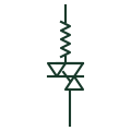
A shunt reactor in series with anti-parallel thyristors whose firing angle sets the reactive power absorbed.
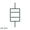
A three-phase capacitor assembly provides a documented reactive-power function connected to the power circuit.
Power factor correction capacitors with series reactors that tune each step below the lowest significant harmonic.
Elora Grid helps electrical teams work with drawings, specifications and equipment information. Explore the drafting workflow or join the early-access waitlist.