SOE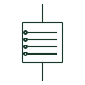
Sequence-of-events recorder
Recorder that timestamps changes of state on many binary inputs so the order of operations can be reconstructed.
Schematic
Recorder that captures analogue waveforms and binary signals before and after a trigger for fault analysis.
In plain English
A disturbance recorder captures sampled current and voltage waveforms together with breaker and protection contact states when a trigger occurs. Pre-fault and post-fault data let engineers check how protection performed, so the recorder is drawn with its analogue inputs from CTs and VTs and its binary inputs from trip and position contacts.
Many protection relays now include this function, so a separate recorder symbol usually indicates a dedicated substation-wide unit. The symbol does not show trigger conditions, sample rate or record length, and records are commonly exchanged in a standard file format that should be named in the specification.
Trace analogue inputs to their CTs and VTs. List binary inputs and their sources. A disturbance recorder stores high-rate waveforms around an event; a sequence-of-events recorder stores timestamped contact changes only.
Recorder that captures analogue waveforms and binary signals before and after a trigger for fault analysis. A disturbance recorder stores high-rate waveforms around an event; a sequence-of-events recorder stores timestamped contact changes only.
Read the source: Relion 620: functions, codes and symbols · PowerLogic ION9000 user manual
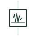
A disturbance recorder captures sampled current and voltage waveforms together with breaker and protection contact states when a trigger occurs. Pre-fault and post-fault data let engineers check how protection performed, so the recorder is drawn with its analogue inputs from CTs and VTs and its binary inputs from trip and position contacts.
Many protection relays now include this function, so a separate recorder symbol usually indicates a dedicated substation-wide unit. The symbol does not show trigger conditions, sample rate or record length, and records are commonly exchanged in a standard file format that should be named in the specification.
A disturbance recorder stores high-rate waveforms around an event; a sequence-of-events recorder stores timestamped contact changes only.
These public references support the explanation and provide further detail. Their graphics and downloadable files remain with their publishers.
Public relay function list including disturbance recording within protection IEDs.
Public meter manual describing measurement, logging and recording features of a revenue and power-quality meter.
This illustration was authored independently by Elora Grid to explain the concept. It is not reproduced from a customer drawing, an official standard graphic or a manufacturer CAD file. Its correspondence to an exact IEC or IEEE symbol identifier has not been certified.
SVG and DXF downloads contain this original artwork. DXF uses unscaled drawing units; a GA envelope supplies no product dimensions, clearances or fabrication information. Original artwork is available under CC BY 4.0. Third-party references retain their own terms.
Recorder that timestamps changes of state on many binary inputs so the order of operations can be reconstructed.
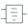
Single relay block on an SLD that lists the protection functions it provides, with CT, VT and trip connections.

Instrument that displays the waveform of a signal against time, drawn with a waveform inside the instrument outline.
Elora Grid helps electrical teams work with drawings, specifications and equipment information. Explore the drafting workflow or join the early-access waitlist.