INV DC-AC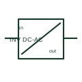
DC-to-AC inverter
A DC/AC inverter converts a documented DC supply into an AC output.
SLD / Schematic
In plain English
A charger power module is one conversion building block within a charging system.
A charging station can coordinate several selected modules to supply its DC output.
Show the module as a conversion building block inside the station, rather than the complete charger. Label its power input, controlled output and supervisory interface. Where several modules are used, identify their arrangement instead of assuming their output ratings can simply be added.
The selected station can also need input distribution, protection, cooling, metering, vehicle communication and output switching. A power-module drawing does not automatically supply those surrounding systems.
Read the source: DC fast charging architecture
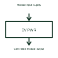
The power module is not the complete station, communications interface or protective installation.
These public references support the explanation and provide further detail. Their graphics and downloadable files remain with their publishers.
DC fast charging architecture: public technical context for the named function. Product and compliance details remain with the publisher.
This illustration was authored independently by Elora Grid to explain the concept. It is not reproduced from a customer drawing, an official standard graphic or a manufacturer CAD file. Its correspondence to an exact IEC or IEEE symbol identifier has not been certified.
SVG and DXF downloads contain this original artwork. DXF uses unscaled drawing units; a GA envelope supplies no product dimensions, clearances or fabrication information. Original artwork is available under CC BY 4.0. Third-party references retain their own terms.
A DC/AC inverter converts a documented DC supply into an AC output.
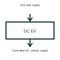
A DC charging station performs offboard power conversion and supplies controlled DC to the vehicle interface.
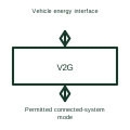
A bidirectional charging interface supports controlled energy transfer in both permitted directions.
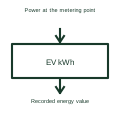
Charging energy measurement records the electrical energy passing through the defined measuring point.
Elora Grid helps electrical teams work with drawings, specifications and equipment information. Explore the drafting workflow or join the early-access waitlist.