HT0_TW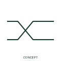
Twisted-pair indication
A twisted-pair indication identifies the documented association of two conductors as a twisted pair.
IEC
A wavy conductor line showing a connection that must flex, such as a lead to moving equipment or a vibration break.
In plain English
The flexible conductor mark replaces a straight run of conductor with a wave or loop to show that the connection is intended to bend in service. Typical uses are leads to hinged doors, pendant control stations, crane festoons, motor terminal boxes on resilient mounts and short links that absorb thermal movement between busbars and equipment.
On a schematic the wave says nothing about the cable construction. Stranding class, insulation type, bending radius and the number of operating cycles must come from the cable schedule or equipment specification. A drafter should not use the wave simply to make a long wire look tidy, because a reader will assume a moving or vibrating part exists at that point.
Look for the moving or vibrating item at one end of the wavy section. Check the cable schedule for a flexible stranding class and any drag-chain or festoon rating. A flexible conductor bends in service; a twisted-pair mark shows conductors twisted together for noise rejection and implies nothing about movement.
A wavy conductor line showing a connection that must flex, such as a lead to moving equipment or a vibration break. A flexible conductor bends in service; a twisted-pair mark shows conductors twisted together for noise rejection and implies nothing about movement.
Read the source: IEC-60617 symbol preview directory · IEEE/ANSI 315-1975: graphic symbols for electrical and electronics diagrams
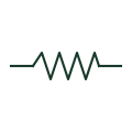
The flexible conductor mark replaces a straight run of conductor with a wave or loop to show that the connection is intended to bend in service. Typical uses are leads to hinged doors, pendant control stations, crane festoons, motor terminal boxes on resilient mounts and short links that absorb thermal movement between busbars and equipment.
On a schematic the wave says nothing about the cable construction. Stranding class, insulation type, bending radius and the number of operating cycles must come from the cable schedule or equipment specification. A drafter should not use the wave simply to make a long wire look tidy, because a reader will assume a moving or vibrating part exists at that point.
A flexible conductor bends in service; a twisted-pair mark shows conductors twisted together for noise rejection and implies nothing about movement.
These public references support the explanation and provide further detail. Their graphics and downloadable files remain with their publishers.
Public IEC-60617 symbol preview directory used to locate conductor and connection families.
Graphic-symbol standards context for conductor forms; not a source of reproduced artwork.
This illustration was authored independently by Elora Grid to explain the concept. It is not reproduced from a customer drawing, an official standard graphic or a manufacturer CAD file. Its correspondence to an exact IEC or IEEE symbol identifier has not been certified.
SVG and DXF downloads contain this original artwork. DXF uses unscaled drawing units; a GA envelope supplies no product dimensions, clearances or fabrication information. Original artwork is available under CC BY 4.0. Third-party references retain their own terms.
A twisted-pair indication identifies the documented association of two conductors as a twisted pair.
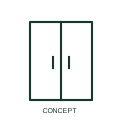
A flexible busbar connection joins selected conductors or equipment terminals.

An identified electrical connection point linking schematic and wiring information.
Elora Grid helps electrical teams work with drawings, specifications and equipment information. Explore the drafting workflow or join the early-access waitlist.