CHG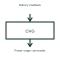
Battery charger controller
A battery charger controller manages the charging process for the selected battery system.
Schematic
A rectifier charger that holds a stationary battery at float voltage and can apply a higher boost or equalise voltage.
In plain English
A float and boost charger is the rectifier that maintains a stationary battery, typically for switchgear tripping supplies, telecom or a microgrid DC bus. In float mode it supplies the standing DC load and a small trickle current, while boost or equalise mode raises the voltage to recharge the battery quickly after a discharge or to equalise lead-acid cells.
Drawings show a rectifier block with an AC input breaker, DC output to the battery and the DC distribution board, and often a blocking diode or dropping diode chain to keep load voltage within limits during boost. Alarm contacts for charger failure, earth fault and low voltage are drawn on the control schematic.
The symbol does not state the current limit, whether the charger alone can carry the full load without the battery, or temperature compensation of float voltage. These matter for sizing and for battery life, so they must be in the specification.
A rectifier charger that holds a stationary battery at float voltage and can apply a higher boost or equalise voltage. A station charger is a power rectifier supplying load and battery; a battery charger controller is an integrated circuit inside smaller equipment.
Read the source: Skylla-IP65 official product and documents · DC UPS, AC UPS and capacitor buffer modules
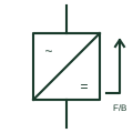
A float and boost charger is the rectifier that maintains a stationary battery, typically for switchgear tripping supplies, telecom or a microgrid DC bus. In float mode it supplies the standing DC load and a small trickle current, while boost or equalise mode raises the voltage to recharge the battery quickly after a discharge or to equalise lead-acid cells.
Drawings show a rectifier block with an AC input breaker, DC output to the battery and the DC distribution board, and often a blocking diode or dropping diode chain to keep load voltage within limits during boost. Alarm contacts for charger failure, earth fault and low voltage are drawn on the control schematic.
The symbol does not state the current limit, whether the charger alone can carry the full load without the battery, or temperature compensation of float voltage. These matter for sizing and for battery life, so they must be in the specification.
A station charger is a power rectifier supplying load and battery; a battery charger controller is an integrated circuit inside smaller equipment.
These public references support the explanation and provide further detail. Their graphics and downloadable files remain with their publishers.
Public battery charger documentation context.
Public DC supply and UPS function context.
This illustration was authored independently by Elora Grid to explain the concept. It is not reproduced from a customer drawing, an official standard graphic or a manufacturer CAD file. Its correspondence to an exact IEC or IEEE symbol identifier has not been certified.
SVG and DXF downloads contain this original artwork. DXF uses unscaled drawing units; a GA envelope supplies no product dimensions, clearances or fabrication information. Original artwork is available under CC BY 4.0. Third-party references retain their own terms.
A battery charger controller manages the charging process for the selected battery system.
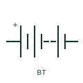
IEEE-style multi-cell battery drawn as alternating long and short plates, with polarity marked, for American drawing sets.

A battery charger maintains a specified battery supply or starting battery system.
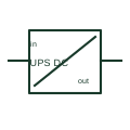
A DC UPS maintains a documented DC load supply during a specified input interruption using an associated energy store.
Elora Grid helps electrical teams work with drawings, specifications and equipment information. Explore the drafting workflow or join the early-access waitlist.