GRID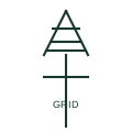
Utility grid connection
The symbol for the external utility network as a supply source at the top of a single-line diagram.
SLD
A voltage source behind an impedance used in study diagrams to represent the external network at a defined fault level.
In plain English
A grid equivalent source represents the upstream network in load flow, short circuit and stability studies as an ideal voltage source behind an impedance. The impedance is calculated from the declared fault level and X/R ratio at the connection point, often with separate maximum and minimum cases.
Study single-line diagrams draw it as a circle with a sine wave followed by an impedance element, labelled with the fault level in MVA or kA and the X/R ratio. Microgrid studies use it to test both strong and weak network conditions before islanding scenarios are modelled.
The equivalent is only valid near the declared fault level; it cannot represent upstream dynamics such as voltage control or frequency response unless additional models are attached. The symbol does not tell you which study case it belongs to.
A voltage source behind an impedance used in study diagrams to represent the external network at a defined fault level. A grid equivalent is a study model; a utility grid connection symbol represents the real supply on construction drawings.
Read the source: IEC graphical symbols for diagrams · IEEE/ANSI 315-1975: graphic symbols for electrical and electronics diagrams
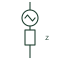
A grid equivalent source represents the upstream network in load flow, short circuit and stability studies as an ideal voltage source behind an impedance. The impedance is calculated from the declared fault level and X/R ratio at the connection point, often with separate maximum and minimum cases.
Study single-line diagrams draw it as a circle with a sine wave followed by an impedance element, labelled with the fault level in MVA or kA and the X/R ratio. Microgrid studies use it to test both strong and weak network conditions before islanding scenarios are modelled.
The equivalent is only valid near the declared fault level; it cannot represent upstream dynamics such as voltage control or frequency response unless additional models are attached. The symbol does not tell you which study case it belongs to.
A grid equivalent is a study model; a utility grid connection symbol represents the real supply on construction drawings.
These public references support the explanation and provide further detail. Their graphics and downloadable files remain with their publishers.
IEC graphical symbol context for sources and impedances.
IEEE/ANSI graphic-symbol context for sources.
This illustration was authored independently by Elora Grid to explain the concept. It is not reproduced from a customer drawing, an official standard graphic or a manufacturer CAD file. Its correspondence to an exact IEC or IEEE symbol identifier has not been certified.
SVG and DXF downloads contain this original artwork. DXF uses unscaled drawing units; a GA envelope supplies no product dimensions, clearances or fabrication information. Original artwork is available under CC BY 4.0. Third-party references retain their own terms.
The symbol for the external utility network as a supply source at the top of a single-line diagram.
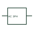
A three-phase AC source identifies a documented three-phase supply boundary.

A reactor is an inductive component used for a documented power-circuit purpose.
Elora Grid helps electrical teams work with drawings, specifications and equipment information. Explore the drafting workflow or join the early-access waitlist.