PCC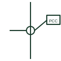
Point of common coupling
A marker on a single-line diagram identifying where a customer installation or microgrid meets the public network.
SLD
The symbol for the external utility network as a supply source at the top of a single-line diagram.
In plain English
The utility grid connection symbol represents the public supply network as seen from the installation. It is drawn at the top or edge of a single-line diagram to show where power enters, and in a microgrid it is one of several sources, typically the reference source when the microgrid is grid-connected.
Common forms include a lattice tower glyph, a circle with a sine wave, a set of arrows into the busbar or a box labelled UTILITY or GRID. Voltage, prospective fault level and earthing system of the supply are written beside it.
The symbol does not show the network operator protection or reclose behaviour, which affects whether downstream generation must disconnect quickly. Those details come from the connection agreement and are usually noted on the drawing.
The symbol for the external utility network as a supply source at the top of a single-line diagram. A utility connection represents the external network; a grid equivalent source is a study model with defined impedance.
Read the source: AutoCAD Electrical: Earthing, sources and surge protection · Electrical installation design methodology and references
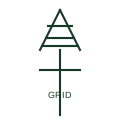
The utility grid connection symbol represents the public supply network as seen from the installation. It is drawn at the top or edge of a single-line diagram to show where power enters, and in a microgrid it is one of several sources, typically the reference source when the microgrid is grid-connected.
Common forms include a lattice tower glyph, a circle with a sine wave, a set of arrows into the busbar or a box labelled UTILITY or GRID. Voltage, prospective fault level and earthing system of the supply are written beside it.
The symbol does not show the network operator protection or reclose behaviour, which affects whether downstream generation must disconnect quickly. Those details come from the connection agreement and are usually noted on the drawing.
A utility connection represents the external network; a grid equivalent source is a study model with defined impedance.
These public references support the explanation and provide further detail. Their graphics and downloadable files remain with their publishers.
Public earthing and source symbol context.
Public electrical installation design references covering supply characteristics.
This illustration was authored independently by Elora Grid to explain the concept. It is not reproduced from a customer drawing, an official standard graphic or a manufacturer CAD file. Its correspondence to an exact IEC or IEEE symbol identifier has not been certified.
SVG and DXF downloads contain this original artwork. DXF uses unscaled drawing units; a GA envelope supplies no product dimensions, clearances or fabrication information. Original artwork is available under CC BY 4.0. Third-party references retain their own terms.
A marker on a single-line diagram identifying where a customer installation or microgrid meets the public network.
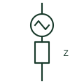
A voltage source behind an impedance used in study diagrams to represent the external network at a defined fault level.
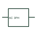
A three-phase AC source identifies a documented three-phase supply boundary.
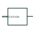
A substation representation identifies a documented facility boundary in a network or system diagram.
Elora Grid helps electrical teams work with drawings, specifications and equipment information. Explore the drafting workflow or join the early-access waitlist.