SAT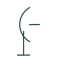
Dish antenna symbol
Symbol for a parabolic dish antenna used for satellite reception or microwave links.
IEC
General antenna symbol, a vertical line ending in a V or triangle, used on communications and TV distribution drawings.
In plain English
The antenna symbol is a vertical feed line ending in an open triangle or V. It is used for TV and FM aerials, wireless bridge antennas, cellular router antennas and radio links on schematics and site plans.
On a site plan the symbol marks the mast or roof location; on a schematic it marks the RF connection point of a radio device. The coaxial cable route and lightning protection are separate design items that the plan should show.
The general symbol does not indicate the type, frequency band or gain of the antenna. Directional antennas may add a direction mark.
General antenna symbol, a vertical line ending in a V or triangle, used on communications and TV distribution drawings. A dish antenna has a parabolic reflector; the general antenna symbol has no reflector.
Read the source: IEC graphical symbols for diagrams · Cables and antennas for industrial network devices · Autodesk IEC-60617 preview: Propagation and signal-flow qualifiers
IEC 60617 installation-plan style (architectural and topographical installation symbols); independently drawn, not certified IEC geometry or a database identifier.
Shown as an independently authored educational illustration. Use the cited publication and drawing legend to verify the required drafting form.

The antenna symbol is a vertical feed line ending in an open triangle or V. It is used for TV and FM aerials, wireless bridge antennas, cellular router antennas and radio links on schematics and site plans.
On a site plan the symbol marks the mast or roof location; on a schematic it marks the RF connection point of a radio device. The coaxial cable route and lightning protection are separate design items that the plan should show.
The general symbol does not indicate the type, frequency band or gain of the antenna. Directional antennas may add a direction mark.
A dish antenna has a parabolic reflector; the general antenna symbol has no reflector.
These public references support the explanation and provide further detail. Their graphics and downloadable files remain with their publishers.
IEC graphical symbol context for installation and communication plans; independently drawn here.
Public accessory page covering antennas and RF cables for network devices.
Public IEC-oriented propagation and signal-flow qualifiers used on communication symbols.
This illustration was authored independently by Elora Grid to explain the concept. It is not reproduced from a customer drawing, an official standard graphic or a manufacturer CAD file. Its correspondence to an exact IEC or IEEE symbol identifier has not been certified.
SVG and DXF downloads contain this original artwork. DXF uses unscaled drawing units; a GA envelope supplies no product dimensions, clearances or fabrication information. Original artwork is available under CC BY 4.0. Third-party references retain their own terms.
Symbol for a parabolic dish antenna used for satellite reception or microwave links.

Plan symbol for a television or cable TV outlet with a coaxial connection.
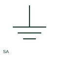
A surge arrester diverts a documented surge-related current through its protective path.
Elora Grid helps electrical teams work with drawings, specifications and equipment information. Explore the drafting workflow or join the early-access waitlist.