CTR DIV10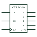
IEC decade counter (CTR DIV10)
IEC counter marked CTR DIV10, counting through ten states with BCD-weighted outputs.
IEC
IEC coder marked BCD/7SEG converting a 4-bit BCD input into seven segment-drive outputs a to g.
In plain English
The BCD-to-seven-segment decoder is an X/Y coder with the additional drawing mark BCD/7SEG, sometimes written BCD/7-SEG. Inputs are weighted 1, 2, 4 and 8 and outputs are labelled a to g for the display segments. Many devices add lamp test and blanking inputs shown with their own labels.
Seven-segment decoders appear on drawings for local numeric displays, counters and older instrument panels. The output stage type matters: many drivers have open-collector outputs intended to sink LED or lamp current, which should be shown with the open-circuit additional drawing mark.
The symbol does not state segment current, display type (common anode or cathode) or how non-BCD codes are displayed. Those come from the device data and display selection.
IEC coder marked BCD/7SEG converting a 4-bit BCD input into seven segment-drive outputs a to g. A BIN/OCT decoder activates one output per code; this coder activates a pattern of segments.
Read the source: Overview of IEEE Standard 91-1984: explanation of logic symbols (SDYZ001A) · SN74LS47 BCD-to-seven-segment decoders/drivers
Qualifying-symbol and dependency conventions as explained in TI's public overview of IEEE Std 91-1984, which incorporates IEC 617-12 work. Independent educational drawing; not certified IEC geometry or an IEC database identifier.
Shown as an independently authored educational illustration. Use the cited publication and drawing legend to verify the required drafting form.
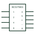
The BCD-to-seven-segment decoder is an X/Y coder with the qualifier BCD/7SEG, sometimes written BCD/7-SEG. Inputs are weighted 1, 2, 4 and 8 and outputs are labelled a to g for the display segments. Many devices add lamp test and blanking inputs shown with their own labels.
Seven-segment decoders appear on drawings for local numeric displays, counters and older instrument panels. The output stage type matters: many drivers have open-collector outputs intended to sink LED or lamp current, which should be shown with the open-circuit qualifier.
The symbol does not state segment current, display type (common anode or cathode) or how non-BCD codes are displayed. Those come from the device data and display selection.
A BIN/OCT decoder activates one output per code; this coder activates a pattern of segments.
These public references support the explanation and provide further detail. Their graphics and downloadable files remain with their publishers.
Lists BIN/7-SEG style coder designations.
Manufacturer BCD-to-seven-segment decoder/driver documentation.
This illustration was authored independently by Elora Grid to explain the concept. It is not reproduced from a customer drawing, an official standard graphic or a manufacturer CAD file. Its correspondence to an exact IEC or IEEE symbol identifier has not been certified.
SVG and DXF downloads contain this original artwork. DXF uses unscaled drawing units; a GA envelope supplies no product dimensions, clearances or fabrication information. Original artwork is available under CC BY 4.0. Third-party references retain their own terms.
IEC counter marked CTR DIV10, counting through ten states with BCD-weighted outputs.
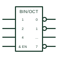
IEC coder marked BIN/OCT or similar, converting a binary input code into one active output.
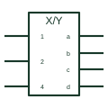
IEC element marked X/Y, the general coder converting one code, named X, into another, named Y.
Elora Grid helps electrical teams work with drawings, specifications and equipment information. Explore the drafting workflow or join the early-access waitlist.