SRG8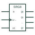
IEC shift register (SRGm)
IEC register marked SRGm with m stages; the clock carries the shift arrow and moves data one place each cycle.
IEC
IEC shift register with mode inputs that select shift right, shift left, parallel load or hold.
In plain English
A universal shift register is drawn as an SRG element with two mode-select inputs grouped to produce modes 0 to 3. The clock label shows shift right under one mode and shift left under another, while data inputs are labelled with their mode and control numbers, such as 1,4D for serial right input and 3,4D for parallel load.
These devices are used in data conversion, sequence generation and bidirectional serial links. Reading the compound labels left to right, mode first then clock, tells you exactly when each input is used.
The symbol does not state which mode is safe to change during clocking. Mode changes are normally made with the clock inactive.
IEC shift register with mode inputs that select shift right, shift left, parallel load or hold. A single-direction SRG register has no mode inputs and shifts only one way.
Read the source: Overview of IEEE Standard 91-1984: explanation of logic symbols (SDYZ001A)
Qualifying-symbol and dependency conventions as explained in TI's public overview of IEEE Std 91-1984, which incorporates IEC 617-12 work. Independent educational drawing; not certified IEC geometry or an IEC database identifier.
Shown as an independently authored educational illustration. Use the cited publication and drawing legend to verify the required drafting form.
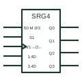
A universal shift register is drawn as an SRG element with two mode-select inputs grouped to produce modes 0 to 3. The clock label shows shift right under one mode and shift left under another, while data inputs are labelled with their mode and control numbers, such as 1,4D for serial right input and 3,4D for parallel load.
These devices are used in data conversion, sequence generation and bidirectional serial links. Reading the compound labels left to right, mode first then clock, tells you exactly when each input is used.
The symbol does not state which mode is safe to change during clocking. Mode changes are normally made with the clock inactive.
A single-direction SRG register has no mode inputs and shifts only one way.
These public references support the explanation and provide further detail. Their graphics and downloadable files remain with their publishers.
Shift right and left labels and M dependency examples.
This illustration was authored independently by Elora Grid to explain the concept. It is not reproduced from a customer drawing, an official standard graphic or a manufacturer CAD file. Its correspondence to an exact IEC or IEEE symbol identifier has not been certified.
SVG and DXF downloads contain this original artwork. DXF uses unscaled drawing units; a GA envelope supplies no product dimensions, clearances or fabrication information. Original artwork is available under CC BY 4.0. Third-party references retain their own terms.
IEC register marked SRGm with m stages; the clock carries the shift arrow and moves data one place each cycle.
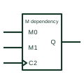
Dependency label Mm used to show operating modes; affected inputs and outputs act only in the selected mode.
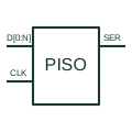
Loads a parallel word and presents its bits through a serial shift output.
Elora Grid helps electrical teams work with drawings, specifications and equipment information. Explore the drafting workflow or join the early-access waitlist.