W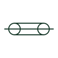
Coaxial cable
A centre conductor drawn within a concentric outer conductor, used for RF, video and some high-frequency measurement leads.
IEC
A coaxial cable whose outer conductor is drawn connected to earth, recording the reference point of the RF or signal return.
In plain English
This form adds an earth connection to the outer conductor of a coaxial cable. On antenna systems the outer conductor is normally bonded to the building earth where it enters, often through a lightning arrester or earthing kit, and the drawing should show that bonding explicitly.
The earth mark on the outer conductor is not a statement that the inner conductor is protected from surges. Surge protection devices on the inner conductor are separate symbols. Reading the earth location also tells you whether the coax forms an earth loop between two buildings, which matters for interference and safety.
Locate the entry point bonding for antenna coax. Check for earth loops where both ends of the outer conductor are earthed in separate buildings. Earthing the outer conductor sets its reference; it is not the same as a coaxial surge protector, which clamps the inner conductor.
A coaxial cable whose outer conductor is drawn connected to earth, recording the reference point of the RF or signal return. Earthing the outer conductor sets its reference; it is not the same as a coaxial surge protector, which clamps the inner conductor.
Read the source: IEC-60617 symbol preview directory · AutoCAD Electrical: Earthing, sources and surge protection
Independent IEC-context combination of coaxial and earth forms; not certified IEC geometry.
Shown as an independently authored educational illustration. Use the cited publication and drawing legend to verify the required drafting form.
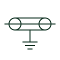
This form adds an earth connection to the outer conductor of a coaxial cable. On antenna systems the outer conductor is normally bonded to the building earth where it enters, often through a lightning arrester or earthing kit, and the drawing should show that bonding explicitly.
The earth mark on the outer conductor is not a statement that the inner conductor is protected from surges. Surge protection devices on the inner conductor are separate symbols. Reading the earth location also tells you whether the coax forms an earth loop between two buildings, which matters for interference and safety.
Earthing the outer conductor sets its reference; it is not the same as a coaxial surge protector, which clamps the inner conductor.
These public references support the explanation and provide further detail. Their graphics and downloadable files remain with their publishers.
Public directory of IEC-oriented symbol families.
Public IEC-oriented earth forms used on the outer conductor.
This illustration was authored independently by Elora Grid to explain the concept. It is not reproduced from a customer drawing, an official standard graphic or a manufacturer CAD file. Its correspondence to an exact IEC or IEEE symbol identifier has not been certified.
SVG and DXF downloads contain this original artwork. DXF uses unscaled drawing units; a GA envelope supplies no product dimensions, clearances or fabrication information. Original artwork is available under CC BY 4.0. Third-party references retain their own terms.
A centre conductor drawn within a concentric outer conductor, used for RF, video and some high-frequency measurement leads.
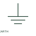
An earth connection identifies a documented circuit connection to earth.
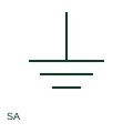
A surge arrester diverts a documented surge-related current through its protective path.
Elora Grid helps electrical teams work with drawings, specifications and equipment information. Explore the drafting workflow or join the early-access waitlist.