ISO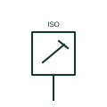
Local isolator plan mark
Plan mark for a local isolating switch placed beside fixed equipment for safe maintenance.
IEC
Plan mark for the double-pole control switch and outlet serving a fixed cooking appliance.
In plain English
A cooker control unit is a high-current double-pole switch, sometimes with an auxiliary socket outlet, that controls and isolates a fixed cooker or hob. Plan legends usually draw a switch box with the letters CCU or a cooker mark, placed within reach of the appliance but not above the hob.
The symbol tells the electrician to run a dedicated radial circuit sized for the appliance, often 32 A or larger, and to install a separate cooker connection plate behind the appliance. Two symbols are often shown together: the control unit on the splashback and the connection outlet low behind the cooker. It does not show the cable size or the diversity used in the design. Those belong in the circuit schedule.
Look for a paired connection plate behind the appliance position. Check whether the unit includes an auxiliary outlet. A general isolator mark has no auxiliary outlet and is not tied to a cooking appliance; the cooker control unit is a dedicated appliance accessory.
Plan mark for the double-pole control switch and outlet serving a fixed cooking appliance. A general isolator mark has no auxiliary outlet and is not tied to a cooking appliance; the cooker control unit is a dedicated appliance accessory.
Read the source: IEC graphical symbols for diagrams · Elementary switching devices · Electrical installation design methodology and references
IEC 60617 installation-plan style (architectural and topographical installation symbols); independently drawn, not certified IEC geometry or a database identifier.
Shown as an independently authored educational illustration. Use the cited publication and drawing legend to verify the required drafting form.
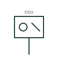
A cooker control unit is a high-current double-pole switch, sometimes with an auxiliary socket outlet, that controls and isolates a fixed cooker or hob. Plan legends usually draw a switch box with the letters CCU or a cooker mark, placed within reach of the appliance but not above the hob.
The symbol tells the electrician to run a dedicated radial circuit sized for the appliance, often 32 A or larger, and to install a separate cooker connection plate behind the appliance. Two symbols are often shown together: the control unit on the splashback and the connection outlet low behind the cooker. It does not show the cable size or the diversity used in the design. Those belong in the circuit schedule.
A general isolator mark has no auxiliary outlet and is not tied to a cooking appliance; the cooker control unit is a dedicated appliance accessory.
These public references support the explanation and provide further detail. Their graphics and downloadable files remain with their publishers.
IEC committee context for graphical symbols used in diagrams and installation documents; not a source of reproduced artwork.
Explains elementary switching functions such as isolation, control and functional switching.
Installation design methodology context: circuits, outlets and final distribution are planned before symbols are placed.
This illustration was authored independently by Elora Grid to explain the concept. It is not reproduced from a customer drawing, an official standard graphic or a manufacturer CAD file. Its correspondence to an exact IEC or IEEE symbol identifier has not been certified.
SVG and DXF downloads contain this original artwork. DXF uses unscaled drawing units; a GA envelope supplies no product dimensions, clearances or fabrication information. Original artwork is available under CC BY 4.0. Third-party references retain their own terms.
Plan mark for a local isolating switch placed beside fixed equipment for safe maintenance.

Plan mark for a cord or flex outlet where fixed equipment is connected directly at a wall plate.
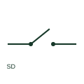
A switch-disconnector combines operational switching with an isolation function.
Elora Grid helps electrical teams work with drawings, specifications and equipment information. Explore the drafting workflow or join the early-access waitlist.