INTEGRATOR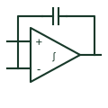
Op-amp integrator
Uses a documented amplifier/capacitor feedback arrangement to obtain an integrating signal response.
Schematic
Analogue element marked with an integral sign; the output is proportional to the time integral of the input.
In plain English
The integrator element shows the integral sign inside a rectangular analogue element, usually with an amplifier mark. Its output changes at a rate proportional to the input, so a constant input produces a ramp. Reset or initial-condition inputs may be added to set the starting value.
Integrators appear in PI controllers, ramp generators and charge measurement. On the drawing, the time constant and any reset arrangement should be stated, because without them the element can drift to saturation.
The element does not specify the realisation. An op-amp with a feedback capacitor is common, but digital integration in a controller is drawn the same way on functional diagrams.
Analogue element marked with an integral sign; the output is proportional to the time integral of the input. The differentiator element uses d/dt and responds to rate of change rather than accumulated value.
Read the source: IEC graphical symbols for diagrams · Integrator circuit reference, SBOA275
IEC-style rectangular analogue element presentation; the IEC graphical symbols programme is cited for context only. Independent educational drawing; not certified IEC geometry or an IEC database identifier. The counterpart is the matching functional concept; no equivalence of every detailed standard graphic is asserted.
Shown as an independently authored educational illustration. Use the cited publication and drawing legend to verify the required drafting form.
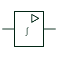
The integrator element shows the integral sign inside a rectangular analogue element, usually with an amplifier mark. Its output changes at a rate proportional to the input, so a constant input produces a ramp. Reset or initial-condition inputs may be added to set the starting value.
Integrators appear in PI controllers, ramp generators and charge measurement. On the drawing, the time constant and any reset arrangement should be stated, because without them the element can drift to saturation.
The element does not specify the realisation. An op-amp with a feedback capacitor is common, but digital integration in a controller is drawn the same way on functional diagrams.
The differentiator element uses d/dt and responds to rate of change rather than accumulated value.
These public references support the explanation and provide further detail. Their graphics and downloadable files remain with their publishers.
IEC graphical symbols programme covering analogue elements; no geometry reproduced.
Manufacturer integrator circuit documentation.
This illustration was authored independently by Elora Grid to explain the concept. It is not reproduced from a customer drawing, an official standard graphic or a manufacturer CAD file. Its correspondence to an exact IEC or IEEE symbol identifier has not been certified.
SVG and DXF downloads contain this original artwork. DXF uses unscaled drawing units; a GA envelope supplies no product dimensions, clearances or fabrication information. Original artwork is available under CC BY 4.0. Third-party references retain their own terms.
Uses a documented amplifier/capacitor feedback arrangement to obtain an integrating signal response.
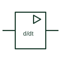
Analogue element marked d/dt whose output is proportional to the rate of change of its input.
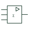
Analogue element with Σ and several inputs, producing an output proportional to the weighted sum of the inputs.
Elora Grid helps electrical teams work with drawings, specifications and equipment information. Explore the drafting workflow or join the early-access waitlist.