▷∞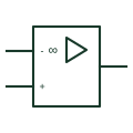
IEC operational amplifier (rectangular form)
Rectangular IEC-style op-amp drawn as a box with an amplifier triangle and an infinity sign for very high gain.
IEC
Analogue element with Σ and several inputs, producing an output proportional to the weighted sum of the inputs.
In plain English
A summing amplifier adds several analogue inputs, each with its own weighting. In IEC-style analogue element diagrams it is drawn as a rectangle with an amplifier mark and the Σ function, with weighting factors written next to each input. The usual circuit realisation is an inverting op-amp with one input resistor per signal.
Summers appear in control loops for combining set-point and feedforward signals, in audio-style mixing of measurements, and in analogue computation. The weighting factors and the sign of the output must be stated because an inverting realisation reverses polarity.
The element does not show the resistor network that sets the weights. For a construction schematic, the op-amp circuit with values should be drawn or referenced.
Analogue element with Σ and several inputs, producing an output proportional to the weighted sum of the inputs. The digital Σ adder adds binary words; the analogue summing element adds voltages or currents.
Read the source: IEC graphical symbols for diagrams · University tutorials: amplifier configurations and signal processing
IEC-style rectangular analogue element presentation; the IEC graphical symbols programme is cited for context only. Independent educational drawing; not certified IEC geometry or an IEC database identifier.
Shown as an independently authored educational illustration. Use the cited publication and drawing legend to verify the required drafting form.
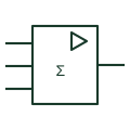
A summing amplifier adds several analogue inputs, each with its own weighting. In IEC-style analogue element diagrams it is drawn as a rectangle with an amplifier mark and the Σ function, with weighting factors written next to each input. The usual circuit realisation is an inverting op-amp with one input resistor per signal.
Summers appear in control loops for combining set-point and feedforward signals, in audio-style mixing of measurements, and in analogue computation. The weighting factors and the sign of the output must be stated because an inverting realisation reverses polarity.
The element does not show the resistor network that sets the weights. For a construction schematic, the op-amp circuit with values should be drawn or referenced.
The digital Σ adder adds binary words; the analogue summing element adds voltages or currents.
These public references support the explanation and provide further detail. Their graphics and downloadable files remain with their publishers.
IEC graphical symbols programme covering analogue elements; no geometry reproduced.
Public tutorial material on op-amp configurations including summing circuits.
This illustration was authored independently by Elora Grid to explain the concept. It is not reproduced from a customer drawing, an official standard graphic or a manufacturer CAD file. Its correspondence to an exact IEC or IEEE symbol identifier has not been certified.
SVG and DXF downloads contain this original artwork. DXF uses unscaled drawing units; a GA envelope supplies no product dimensions, clearances or fabrication information. Original artwork is available under CC BY 4.0. Third-party references retain their own terms.
Rectangular IEC-style op-amp drawn as a box with an amplifier triangle and an infinity sign for very high gain.
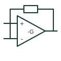
Uses an amplifier feedback connection that produces the documented inverted signal relationship.
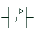
Analogue element marked with an integral sign; the output is proportional to the time integral of the input.
Elora Grid helps electrical teams work with drawings, specifications and equipment information. Explore the drafting workflow or join the early-access waitlist.