PEN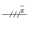
PEN conductor mark
A mark identifying a combined protective and neutral conductor, as used in TN-C sections of a supply.
IEC
A mark on a single-line conductor group identifying which conductor is the neutral, often drawn as a small circle on a stroke.
In plain English
When a single line represents a group of conductors, one of them can be identified as the neutral with a distinct mark on its stroke, together with the letter N where clarity requires. This lets a single-line diagram tell a three-phase three-wire feeder from a three-phase four-wire feeder without expanding to multi-line form.
The mark identifies the neutral but does not say whether the neutral is fully rated, reduced or oversized for harmonic loading. It also does not show where the neutral is earthed. System earthing is a separate decision shown at the source, for example a star point to earth connection or a neutral earthing resistor.
Check whether the feeder carries a neutral before assuming four-wire loads are supported. Look at the source to see how the neutral is earthed. A neutral mark identifies the N conductor; a PEN mark identifies a combined neutral and protective conductor with different switching rules.
A mark on a single-line conductor group identifying which conductor is the neutral, often drawn as a small circle on a stroke. A neutral mark identifies the N conductor; a PEN mark identifies a combined neutral and protective conductor with different switching rules.
Read the source: Definition of standardised earthing schemes · IEC-60617 symbol preview directory
Independent IEC-context illustration; not certified IEC geometry.
Shown as an independently authored educational illustration. Use the cited publication and drawing legend to verify the required drafting form.
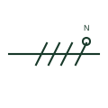
When a single line represents a group of conductors, one of them can be identified as the neutral with a distinct mark on its stroke, together with the letter N where clarity requires. This lets a single-line diagram tell a three-phase three-wire feeder from a three-phase four-wire feeder without expanding to multi-line form.
The mark identifies the neutral but does not say whether the neutral is fully rated, reduced or oversized for harmonic loading. It also does not show where the neutral is earthed. System earthing is a separate decision shown at the source, for example a star point to earth connection or a neutral earthing resistor.
A neutral mark identifies the N conductor; a PEN mark identifies a combined neutral and protective conductor with different switching rules.
These public references support the explanation and provide further detail. Their graphics and downloadable files remain with their publishers.
Public installation-guide definitions of earthing schemes and the role of the neutral conductor.
Public directory of IEC-oriented symbol families.
This illustration was authored independently by Elora Grid to explain the concept. It is not reproduced from a customer drawing, an official standard graphic or a manufacturer CAD file. Its correspondence to an exact IEC or IEEE symbol identifier has not been certified.
SVG and DXF downloads contain this original artwork. DXF uses unscaled drawing units; a GA envelope supplies no product dimensions, clearances or fabrication information. Original artwork is available under CC BY 4.0. Third-party references retain their own terms.
A mark identifying a combined protective and neutral conductor, as used in TN-C sections of a supply.
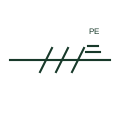
A mark on one stroke of a conductor group identifying the protective earth conductor carried with the circuit.

An accessible-neutral star winding brings the common star point to a documented terminal.
Elora Grid helps electrical teams work with drawings, specifications and equipment information. Explore the drafting workflow or join the early-access waitlist.