PE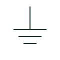
Protective earth
An identified connection serving the protective earthing function.
SLD / Schematic
A mark on one stroke of a conductor group identifying the protective earth conductor carried with the circuit.
In plain English
This mark identifies the protective conductor within a group of conductors drawn as one line. It shows that the circuit carries its own PE conductor to the load, which is how the fault return path for automatic disconnection is provided in TN systems. The letters PE are often written beside the mark.
The mark does not tell you whether the PE is a separate core, the cable armour or a parallel earth continuity conductor. Each option affects earth fault loop impedance differently, so the cable schedule must say which is used. The mark is also distinct from the protective earth terminal symbol, which shows a connection point rather than a conductor in a run.
Confirm what physically forms the PE: a core, armour or separate conductor. Check that the PE size meets the protective conductor sizing rule used. The PE conductor mark identifies a conductor in a run; the protective earth symbol identifies a connection point to the earthing system.
A mark on one stroke of a conductor group identifying the protective earth conductor carried with the circuit. The PE conductor mark identifies a conductor in a run; the protective earth symbol identifies a connection point to the earthing system.
Read the source: Definition of standardised earthing schemes · Earthing connections
Independent IEC-context illustration; not certified IEC geometry.
Shown as an independently authored educational illustration. Use the cited publication and drawing legend to verify the required drafting form.
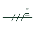
This mark identifies the protective conductor within a group of conductors drawn as one line. It shows that the circuit carries its own PE conductor to the load, which is how the fault return path for automatic disconnection is provided in TN systems. The letters PE are often written beside the mark.
The mark does not tell you whether the PE is a separate core, the cable armour or a parallel earth continuity conductor. Each option affects earth fault loop impedance differently, so the cable schedule must say which is used. The mark is also distinct from the protective earth terminal symbol, which shows a connection point rather than a conductor in a run.
The PE conductor mark identifies a conductor in a run; the protective earth symbol identifies a connection point to the earthing system.
These public references support the explanation and provide further detail. Their graphics and downloadable files remain with their publishers.
Public installation-guide definitions of TN, TT and IT schemes and protective conductors.
Public guide to earthing connection elements.
This illustration was authored independently by Elora Grid to explain the concept. It is not reproduced from a customer drawing, an official standard graphic or a manufacturer CAD file. Its correspondence to an exact IEC or IEEE symbol identifier has not been certified.
SVG and DXF downloads contain this original artwork. DXF uses unscaled drawing units; a GA envelope supplies no product dimensions, clearances or fabrication information. Original artwork is available under CC BY 4.0. Third-party references retain their own terms.
An identified connection serving the protective earthing function.
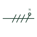
A mark on a single-line conductor group identifying which conductor is the neutral, often drawn as a small circle on a stroke.
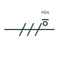
A mark identifying a combined protective and neutral conductor, as used in TN-C sections of a supply.
Elora Grid helps electrical teams work with drawings, specifications and equipment information. Explore the drafting workflow or join the early-access waitlist.