S/H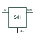
Sample-and-hold amplifier
Acquires an analogue signal during the documented sampling interval and retains a representation during hold.
Schematic
Analogue element marked S/H with a digital control input; it tracks the input, then holds the last value.
In plain English
The sample-and-hold element has an analogue input, an analogue output and a digital control input. While the control is in the sample state the output follows the input; when it changes to hold, the output keeps the last value. IEC-style analogue diagrams mark the digital control input with a # sign, as TI's overview describes for digital inputs on analogue symbols.
Sample-and-hold stages appear in front of analogue-to-digital converters, in multiplexed measurement systems and in peak capture. The drawing should show the control signal source and the hold capacitor, because the hold quality depends on it.
The element does not show droop rate, acquisition time or aperture delay. Those are device and component properties. Check the acquisition interval and hold duration against the measurement sequence and the selected component data.
Analogue element marked S/H with a digital control input; it tracks the input, then holds the last value. An analogue switch alone passes signals; the S/H element includes the hold storage and buffering.
Read the source: Overview of IEEE Standard 91-1984: explanation of logic symbols (SDYZ001A) · AN-1515: sample-and-hold function using an analogue switch
Qualifying-symbol and dependency conventions as explained in TI's public overview of IEEE Std 91-1984, which incorporates IEC 617-12 work. Independent educational drawing; not certified IEC geometry or an IEC database identifier. The counterpart is the matching functional concept; no equivalence of every detailed standard graphic is asserted.
Shown as an independently authored educational illustration. Use the cited publication and drawing legend to verify the required drafting form.
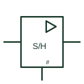
The sample-and-hold element has an analogue input, an analogue output and a digital control input. While the control is in the sample state the output follows the input; when it changes to hold, the output keeps the last value. IEC-style analogue diagrams mark the digital control input with a # sign, as TI's overview describes for digital inputs on analogue symbols.
Sample-and-hold stages appear in front of analogue-to-digital converters, in multiplexed measurement systems and in peak capture. The drawing should show the control signal source and the hold capacitor, because the hold quality depends on it.
The element does not show droop rate, acquisition time or aperture delay. Those are device and component properties. Check the acquisition interval and hold duration against the measurement sequence and the selected component data.
An analogue switch alone passes signals; the S/H element includes the hold storage and buffering.
These public references support the explanation and provide further detail. Their graphics and downloadable files remain with their publishers.
Describes # as the marking for digital inputs on analogue symbols.
Manufacturer sample-and-hold application note.
This illustration was authored independently by Elora Grid to explain the concept. It is not reproduced from a customer drawing, an official standard graphic or a manufacturer CAD file. Its correspondence to an exact IEC or IEEE symbol identifier has not been certified.
SVG and DXF downloads contain this original artwork. DXF uses unscaled drawing units; a GA envelope supplies no product dimensions, clearances or fabrication information. Original artwork is available under CC BY 4.0. Third-party references retain their own terms.
Acquires an analogue signal during the documented sampling interval and retains a representation during hold.
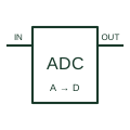
Converts a sampled analogue quantity into the selected digital representation.
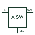
Connects or disconnects an analogue signal path under its documented digital control.
Elora Grid helps electrical teams work with drawings, specifications and equipment information. Explore the drafting workflow or join the early-access waitlist.