HT0_TW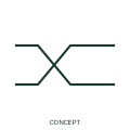
Twisted-pair indication
A twisted-pair indication identifies the documented association of two conductors as a twisted pair.
IEC
Two conductors drawn twisted together inside a screen outline, as used for noise-sensitive signal and communication pairs.
In plain English
The screened twisted pair combines two separate protections against interference. Twisting cancels magnetically induced voltage between the two cores, and the screen intercepts capacitive coupling from nearby power conductors. The form is typical for RS-485 links, 4 to 20 mA loops in noisy plant and resolver or encoder feedback pairs.
On a drawing each screened pair should be identifiable in the core allocation, because a multipair cable may contain several of them plus an overall screen. The symbol does not tell you the characteristic impedance or twist rate, which matter for data networks and must come from the cable specification.
Confirm the pair belongs to the circuit it is drawn on, not split across two circuits. Check how the pair screen is terminated relative to any overall screen. A screened twisted pair adds a shield; the plain twisted-pair indication shows twisting only and no screen.
Two conductors drawn twisted together inside a screen outline, as used for noise-sensitive signal and communication pairs. A screened twisted pair adds a shield; the plain twisted-pair indication shows twisting only and no screen.
Read the source: Autodesk IEC-60617 preview: Cable identification and twisted-pair annotation · IEC-60617 symbol preview directory
Independent combination of IEC-context twisted-pair and screen forms; not certified IEC geometry.
Shown as an independently authored educational illustration. Use the cited publication and drawing legend to verify the required drafting form.
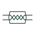
The screened twisted pair combines two separate protections against interference. Twisting cancels magnetically induced voltage between the two cores, and the screen intercepts capacitive coupling from nearby power conductors. The form is typical for RS-485 links, 4 to 20 mA loops in noisy plant and resolver or encoder feedback pairs.
On a drawing each screened pair should be identifiable in the core allocation, because a multipair cable may contain several of them plus an overall screen. The symbol does not tell you the characteristic impedance or twist rate, which matter for data networks and must come from the cable specification.
A screened twisted pair adds a shield; the plain twisted-pair indication shows twisting only and no screen.
These public references support the explanation and provide further detail. Their graphics and downloadable files remain with their publishers.
Public IEC-60617 preview family that includes the twisted-pair marker.
Public directory of IEC-oriented symbol families.
This illustration was authored independently by Elora Grid to explain the concept. It is not reproduced from a customer drawing, an official standard graphic or a manufacturer CAD file. Its correspondence to an exact IEC or IEEE symbol identifier has not been certified.
SVG and DXF downloads contain this original artwork. DXF uses unscaled drawing units; a GA envelope supplies no product dimensions, clearances or fabrication information. Original artwork is available under CC BY 4.0. Third-party references retain their own terms.
A twisted-pair indication identifies the documented association of two conductors as a twisted pair.
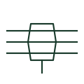
Several conductors enclosed together within one drawn screen, showing an overall shield around a multicore cable.
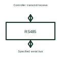
An RS-485 transceiver sends and receives differential serial signals on its specified bus arrangement.
Elora Grid helps electrical teams work with drawings, specifications and equipment information. Explore the drafting workflow or join the early-access waitlist.