TON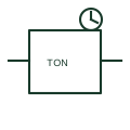
On-delay timer relay
An on-delay timer postpones a specified output transition after its timing condition becomes active.
Schematic
Plan mark for a push switch that turns lights on for a set period, commonly used in stairwells and common corridors.
In plain English
A time-delay push switch, often wired to a staircase timer, turns lighting on when pressed and lets it switch off after a set interval. Plans draw a push-button mark at each push position with a small clock or t tag, and show the timer location in the board where one is used.
Several push switches may be wired in parallel to one timer, so the switching line links them all to a common luminaire group. The electrician reads the plan to run a separate push conductor rather than switched-line wiring.
The plan symbol does not set the delay period or state whether the timer is in the switch or at the board. The specification should give both.
Plan mark for a push switch that turns lights on for a set period, commonly used in stairwells and common corridors. A momentary bell push is not connected to lighting; a time-delay push switch starts a lighting timer.
Read the source: IEC graphical symbols for diagrams · Elementary switching devices
IEC 60617 installation-plan style (architectural and topographical installation symbols); independently drawn, not certified IEC geometry or a database identifier.
Shown as an independently authored educational illustration. Use the cited publication and drawing legend to verify the required drafting form.
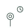
A time-delay push switch, often wired to a staircase timer, turns lighting on when pressed and lets it switch off after a set interval. Plans draw a push-button mark at each push position with a small clock or t tag, and show the timer location in the board where one is used.
Several push switches may be wired in parallel to one timer, so the switching line links them all to a common luminaire group. The electrician reads the plan to run a separate push conductor rather than switched-line wiring.
The plan symbol does not set the delay period or state whether the timer is in the switch or at the board. The specification should give both.
A momentary bell push is not connected to lighting; a time-delay push switch starts a lighting timer.
These public references support the explanation and provide further detail. Their graphics and downloadable files remain with their publishers.
IEC graphical symbol context; independently drawn here.
Context for functional control switching.
This illustration was authored independently by Elora Grid to explain the concept. It is not reproduced from a customer drawing, an official standard graphic or a manufacturer CAD file. Its correspondence to an exact IEC or IEEE symbol identifier has not been certified.
SVG and DXF downloads contain this original artwork. DXF uses unscaled drawing units; a GA envelope supplies no product dimensions, clearances or fabrication information. Original artwork is available under CC BY 4.0. Third-party references retain their own terms.
An on-delay timer postpones a specified output transition after its timing condition becomes active.

Installation plan mark for a momentary push button, such as a door bell push or call button, shown as a small circle with a dot.

Plan mark for a clock-operated time switch that switches a circuit on a programmed schedule.
Elora Grid helps electrical teams work with drawings, specifications and equipment information. Explore the drafting workflow or join the early-access waitlist.