DC-DC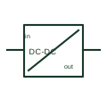
DC-to-DC converter
A DC/DC converter changes a documented DC input into another DC output.
SLD / Schematic
A DC/DC converter with an internal high-frequency transformer that separates input and output galvanically.
In plain English
An isolated DC/DC converter uses a high-frequency transformer between its input and output stages, so the two DC systems have no conductive connection. Isolation lets the output be earthed differently from the input, for example a floating battery bus supplying an earthed control system, or keeps a fault on one side from reaching the other.
Drawings show the DC/DC box with a transformer mark or a pair of coupled coils inside, or a vertical double line across the box. The isolation voltage is a key rating and should be written beside it.
The symbol alone does not state the test voltage or whether the isolation is functional or reinforced for safety. Those properties decide whether the output can be treated as a separated circuit, so they must be read from the product data.
A DC/DC converter with an internal high-frequency transformer that separates input and output galvanically. An isolated converter separates input and output; a non-isolated buck or boost converter shares a common conductor.
Read the source: Power topology selection and public topology tutorials · DIN-rail power supply, buffer, redundancy and UPS families
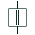
An isolated DC/DC converter uses a high-frequency transformer between its input and output stages, so the two DC systems have no conductive connection. Isolation lets the output be earthed differently from the input, for example a floating battery bus supplying an earthed control system, or keeps a fault on one side from reaching the other.
Drawings show the DC/DC box with a transformer mark or a pair of coupled coils inside, or a vertical double line across the box. The isolation voltage is a key rating and should be written beside it.
The symbol alone does not state the test voltage or whether the isolation is functional or reinforced for safety. Those properties decide whether the output can be treated as a separated circuit, so they must be read from the product data.
An isolated converter separates input and output; a non-isolated buck or boost converter shares a common conductor.
These public references support the explanation and provide further detail. Their graphics and downloadable files remain with their publishers.
Public power topology tutorials including isolated converters.
Public DC power supply and converter family context.
This illustration was authored independently by Elora Grid to explain the concept. It is not reproduced from a customer drawing, an official standard graphic or a manufacturer CAD file. Its correspondence to an exact IEC or IEEE symbol identifier has not been certified.
SVG and DXF downloads contain this original artwork. DXF uses unscaled drawing units; a GA envelope supplies no product dimensions, clearances or fabrication information. Original artwork is available under CC BY 4.0. Third-party references retain their own terms.
A DC/DC converter changes a documented DC input into another DC output.
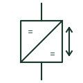
A DC/DC stage that can pass power in either direction, linking a battery or supercapacitor to a DC bus.
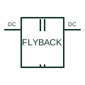
A conversion arrangement that uses coupled magnetic energy storage and transfers energy through the documented switching sequence.
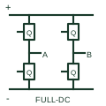
A DC conversion stage using two switching legs to apply the documented waveform to a magnetic primary.
Elora Grid helps electrical teams work with drawings, specifications and equipment information. Explore the drafting workflow or join the early-access waitlist.