LS-GD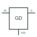
Low-side gate driver
Provides gate-drive current for a power switch referenced to the driver's low-side return.
Schematic
In plain English
A low-side switch controls the return-side connection of a load in its specified circuit.
A load can remain connected to its supply while its return path is switched by a suitable device.
Place the switch between the load and its defined return reference. The load may remain connected to the supply even while this switch is open. Show the complete current loop so a reader does not mistake return-path switching for disconnection of every supply conductor.
Not necessarily. The positive connection can remain present. The drawing must show the actual conductors being interrupted and any separate isolation arrangement.
Read the source: Low-side power switching
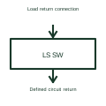
Low-side switching does not necessarily isolate the load from the supply conductor.
These public references support the explanation and provide further detail. Their graphics and downloadable files remain with their publishers.
Low-side power switching: public technical context for the named function. Product and compliance details remain with the publisher.
This illustration was authored independently by Elora Grid to explain the concept. It is not reproduced from a customer drawing, an official standard graphic or a manufacturer CAD file. Its correspondence to an exact IEC or IEEE symbol identifier has not been certified.
SVG and DXF downloads contain this original artwork. DXF uses unscaled drawing units; a GA envelope supplies no product dimensions, clearances or fabrication information. Original artwork is available under CC BY 4.0. Third-party references retain their own terms.
Provides gate-drive current for a power switch referenced to the driver's low-side return.
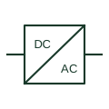
An identified interface converting electrical power between documented circuit forms.

An identified electrical connection point linking schematic and wiring information.
Elora Grid helps electrical teams work with drawings, specifications and equipment information. Explore the drafting workflow or join the early-access waitlist.