ATS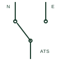
Automatic transfer switch
A mechanically switched changeover device that automatically moves a load from a failed normal source to an alternate source.
SLD / Schematic
An operator-moved changeover switch that selects which of two sources supplies a load, with an off position between them.
In plain English
A manual transfer switch is a changeover switch operated by hand, usually with three positions: source 1, off and source 2. It is common where a portable or small standby generator connects through an inlet, and as a maintenance or bypass switch in larger systems where automatic transfer is not required.
The drawing is a changeover contact with a manual operator mark, often labelled I-0-II, with the two sources above and the load below. The mechanical design prevents both sources being connected at once.
The symbol does not tell you whether the switch can be operated on load, or whether the neutral is switched. Operating procedures, including starting the generator before moving the switch, belong in the operating instructions.
An operator-moved changeover switch that selects which of two sources supplies a load, with an off position between them. A manual transfer switch relies on an operator; an automatic transfer switch senses source failure and acts on its own.
Read the source: Transfer switch fundamentals · Autodesk IEC-60617 preview: Operating-device and function qualifiers
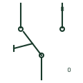
A manual transfer switch is a changeover switch operated by hand, usually with three positions: source 1, off and source 2. It is common where a portable or small standby generator connects through an inlet, and as a maintenance or bypass switch in larger systems where automatic transfer is not required.
The drawing is a changeover contact with a manual operator mark, often labelled I-0-II, with the two sources above and the load below. The mechanical design prevents both sources being connected at once.
The symbol does not tell you whether the switch can be operated on load, or whether the neutral is switched. Operating procedures, including starting the generator before moving the switch, belong in the operating instructions.
A manual transfer switch relies on an operator; an automatic transfer switch senses source failure and acts on its own.
These public references support the explanation and provide further detail. Their graphics and downloadable files remain with their publishers.
Public transfer switch fundamentals.
Public IEC-context operating-device qualifier family for the manual operator mark.
This illustration was authored independently by Elora Grid to explain the concept. It is not reproduced from a customer drawing, an official standard graphic or a manufacturer CAD file. Its correspondence to an exact IEC or IEEE symbol identifier has not been certified.
SVG and DXF downloads contain this original artwork. DXF uses unscaled drawing units; a GA envelope supplies no product dimensions, clearances or fabrication information. Original artwork is available under CC BY 4.0. Third-party references retain their own terms.
A mechanically switched changeover device that automatically moves a load from a failed normal source to an alternate source.

Selects an operating circuit, control source or mode through a manual action.

An equipment assembly connecting a load to the selected supply source.
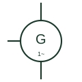
A synchronous alternator delivering a single-phase output, common on small portable and standby generating sets.
Elora Grid helps electrical teams work with drawings, specifications and equipment information. Explore the drafting workflow or join the early-access waitlist.