ATS
Transfer-switch assembly
An equipment assembly connecting a load to the selected supply source.
GA objects
A mechanically switched changeover device that automatically moves a load from a failed normal source to an alternate source.
In plain English
An automatic transfer switch monitors the normal supply and, when voltage or frequency goes out of limits, signals the generator to start and transfers the load to the alternate source once it is ready. When the normal supply returns and is stable, it transfers back after a time delay. Most units use an open-transition break-before-make sequence.
Single-line diagrams show a changeover contact with two incoming poles labelled N and E or S1 and S2 and one outgoing load connection, or two interlocked switching devices. The controller and generator start signal are often noted beside it, and a neutral pole may be switched for separately derived systems.
The symbol does not show the timing, whether the neutral is switched, or whether the transition is open, closed or delayed. Those features determine earthing behaviour, motor reconnection and coordination with the network operator.
A mechanically switched changeover device that automatically moves a load from a failed normal source to an alternate source. An automatic transfer switch operates without an operator; a manual transfer switch needs someone to move it.
Read the source: Transfer switch fundamentals · ATS controllers
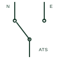
An automatic transfer switch monitors the normal supply and, when voltage or frequency goes out of limits, signals the generator to start and transfers the load to the alternate source once it is ready. When the normal supply returns and is stable, it transfers back after a time delay. Most units use an open-transition break-before-make sequence.
Single-line diagrams show a changeover contact with two incoming poles labelled N and E or S1 and S2 and one outgoing load connection, or two interlocked switching devices. The controller and generator start signal are often noted beside it, and a neutral pole may be switched for separately derived systems.
The symbol does not show the timing, whether the neutral is switched, or whether the transition is open, closed or delayed. Those features determine earthing behaviour, motor reconnection and coordination with the network operator.
An automatic transfer switch operates without an operator; a manual transfer switch needs someone to move it.
These public references support the explanation and provide further detail. Their graphics and downloadable files remain with their publishers.
Public transfer switch fundamentals.
Public automatic transfer controller page describing mains and generator transfer.
This illustration was authored independently by Elora Grid to explain the concept. It is not reproduced from a customer drawing, an official standard graphic or a manufacturer CAD file. Its correspondence to an exact IEC or IEEE symbol identifier has not been certified.
SVG and DXF downloads contain this original artwork. DXF uses unscaled drawing units; a GA envelope supplies no product dimensions, clearances or fabrication information. Original artwork is available under CC BY 4.0. Third-party references retain their own terms.
An equipment assembly connecting a load to the selected supply source.
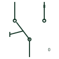
An operator-moved changeover switch that selects which of two sources supplies a load, with an off position between them.
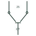
A transfer switch that briefly parallels two synchronised sources so the load moves without interruption.
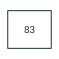
Automatically selects between control circuits or operating sources under defined conditions.
Elora Grid helps electrical teams work with drawings, specifications and equipment information. Explore the drafting workflow or join the early-access waitlist.