Y N
Star winding with accessible neutral
An accessible-neutral star winding brings the common star point to a documented terminal.
SLD / Schematic
A resistor between a transformer or generator neutral and earth that limits earth-fault current to a set value.
In plain English
A neutral earthing resistor connects the star point of a transformer or generator to earth through a defined resistance. It limits earth-fault current, typically to tens or hundreds of amperes on medium-voltage systems and a few amperes on high-resistance earthed low-voltage systems, reducing damage and arc energy while keeping enough current for protection to detect.
Drawings show a resistor between the neutral of a star winding and the earth symbol, often with a current transformer in the neutral lead for earth-fault protection and sometimes a disconnector. The resistor current and time rating, such as 400 A for 10 seconds, are written beside it.
The symbol does not show the resistor's monitoring, which some designs use to detect an open resistor. It also does not show whether generator and transformer neutrals are earthed at the same time, which affects fault current and circulating harmonic currents.
A resistor between a transformer or generator neutral and earth that limits earth-fault current to a set value. A neutral earthing resistor limits fault current resistively; an arc suppression coil compensates capacitive fault current with inductance.
Read the source: Neutral grounding resistor and transformer resources · Residual current and neutral-earthing protection context
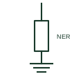
A neutral earthing resistor connects the star point of a transformer or generator to earth through a defined resistance. It limits earth-fault current, typically to tens or hundreds of amperes on medium-voltage systems and a few amperes on high-resistance earthed low-voltage systems, reducing damage and arc energy while keeping enough current for protection to detect.
Drawings show a resistor between the neutral of a star winding and the earth symbol, often with a current transformer in the neutral lead for earth-fault protection and sometimes a disconnector. The resistor current and time rating, such as 400 A for 10 seconds, are written beside it.
The symbol does not show the resistor's monitoring, which some designs use to detect an open resistor. It also does not show whether generator and transformer neutrals are earthed at the same time, which affects fault current and circulating harmonic currents.
A neutral earthing resistor limits fault current resistively; an arc suppression coil compensates capacitive fault current with inductance.
These public references support the explanation and provide further detail. Their graphics and downloadable files remain with their publishers.
Public neutral earthing resistor resource library.
Public neutral earthing and earth-fault protection context.
This illustration was authored independently by Elora Grid to explain the concept. It is not reproduced from a customer drawing, an official standard graphic or a manufacturer CAD file. Its correspondence to an exact IEC or IEEE symbol identifier has not been certified.
SVG and DXF downloads contain this original artwork. DXF uses unscaled drawing units; a GA envelope supplies no product dimensions, clearances or fabrication information. Original artwork is available under CC BY 4.0. Third-party references retain their own terms.
An accessible-neutral star winding brings the common star point to a documented terminal.
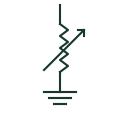
An adjustable reactor between neutral and earth tuned to cancel the network capacitive earth-fault current.
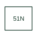
Supervises neutral or residual overcurrent with the configured timing characteristic.

A neutral earthing resistor limits neutral-to-earth fault current in the specified system.
Elora Grid helps electrical teams work with drawings, specifications and equipment information. Explore the drafting workflow or join the early-access waitlist.