VT / PT
Voltage transformer
A transformer providing a voltage signal for metering or protection.
SLD / Schematic
Two phase-to-phase VTs connected in V to provide all three line voltages without a neutral reference.
In plain English
The open-delta or V-V connection uses two double-pole VTs connected between phases, sharing one phase as a common point. It gives all three line-to-line secondary voltages at lower cost than three VTs and is common in MV metering and switchgear where neutral voltages are not needed.
Because there is no neutral reference, phase-to-neutral voltages and zero-sequence voltage cannot be measured. Earth-fault directional elements or meters needing phase-to-neutral inputs therefore cannot be fed from this connection, which the reader must check against the relay requirements.
Identify the common phase shared by both VTs. Check that no connected device needs phase-to-neutral voltage. An open-delta connection uses two phase-to-phase VTs; a broken-delta winding uses three earthed VTs for residual voltage.
Two phase-to-phase VTs connected in V to provide all three line voltages without a neutral reference. An open-delta connection uses two phase-to-phase VTs; a broken-delta winding uses three earthed VTs for residual voltage.
Read the source: Indoor current and voltage transformers · Power, potential and autotransformer symbols

The open-delta or V-V connection uses two double-pole VTs connected between phases, sharing one phase as a common point. It gives all three line-to-line secondary voltages at lower cost than three VTs and is common in MV metering and switchgear where neutral voltages are not needed.
Because there is no neutral reference, phase-to-neutral voltages and zero-sequence voltage cannot be measured. Earth-fault directional elements or meters needing phase-to-neutral inputs therefore cannot be fed from this connection, which the reader must check against the relay requirements.
An open-delta connection uses two phase-to-phase VTs; a broken-delta winding uses three earthed VTs for residual voltage.
These public references support the explanation and provide further detail. Their graphics and downloadable files remain with their publishers.
Public manufacturer overview of indoor current and voltage instrument transformers.
Public potential-transformer symbol family used for context.
This illustration was authored independently by Elora Grid to explain the concept. It is not reproduced from a customer drawing, an official standard graphic or a manufacturer CAD file. Its correspondence to an exact IEC or IEEE symbol identifier has not been certified.
SVG and DXF downloads contain this original artwork. DXF uses unscaled drawing units; a GA envelope supplies no product dimensions, clearances or fabrication information. Original artwork is available under CC BY 4.0. Third-party references retain their own terms.
A transformer providing a voltage signal for metering or protection.
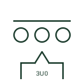
Three single-phase VTs whose residual windings are connected in broken delta to produce the zero-sequence voltage.
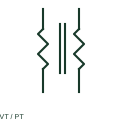
IEEE-oriented graphical reference for voltage transformer, with public vendor evidence and drawing-reading notes.
Elora Grid helps electrical teams work with drawings, specifications and equipment information. Explore the drafting workflow or join the early-access waitlist.