U RES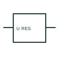
Residual-voltage monitoring relay
A residual-voltage relay responds to the specified residual-voltage measurement.
SLD / Schematic
Three single-phase VTs whose residual windings are connected in broken delta to produce the zero-sequence voltage.
In plain English
In this arrangement three single-phase earthed VTs each carry a residual winding, and the three residual windings are connected in series as a broken delta. In a healthy balanced system the voltage across the open corner is near zero, and during an earth fault it rises towards three times the zero-sequence voltage, which feeds residual voltage and directional earth-fault elements.
A damping resistor is often connected across the broken delta to suppress ferroresonance in isolated or resonant-earthed networks. The symbol does not show that resistor or the earthing of the VT primaries, both of which need explicit detail on the schematic.
Check the primaries are earthed star so zero sequence can be measured. Look for a damping resistor across the open corner. A broken-delta winding measures residual voltage; an open-delta (V-V) connection measures line voltages with two VTs.
Three single-phase VTs whose residual windings are connected in broken delta to produce the zero-sequence voltage. A broken-delta winding measures residual voltage; an open-delta (V-V) connection measures line voltages with two VTs.
Read the source: Indoor current and voltage transformers · Residual current and neutral-earthing protection context
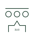
In this arrangement three single-phase earthed VTs each carry a residual winding, and the three residual windings are connected in series as a broken delta. In a healthy balanced system the voltage across the open corner is near zero, and during an earth fault it rises towards three times the zero-sequence voltage, which feeds residual voltage and directional earth-fault elements.
A damping resistor is often connected across the broken delta to suppress ferroresonance in isolated or resonant-earthed networks. The symbol does not show that resistor or the earthing of the VT primaries, both of which need explicit detail on the schematic.
A broken-delta winding measures residual voltage; an open-delta (V-V) connection measures line voltages with two VTs.
These public references support the explanation and provide further detail. Their graphics and downloadable files remain with their publishers.
Public manufacturer overview of indoor current and voltage instrument transformers.
Public context for residual quantities and neutral-earthing protection.
This illustration was authored independently by Elora Grid to explain the concept. It is not reproduced from a customer drawing, an official standard graphic or a manufacturer CAD file. Its correspondence to an exact IEC or IEEE symbol identifier has not been certified.
SVG and DXF downloads contain this original artwork. DXF uses unscaled drawing units; a GA envelope supplies no product dimensions, clearances or fabrication information. Original artwork is available under CC BY 4.0. Third-party references retain their own terms.
A residual-voltage relay responds to the specified residual-voltage measurement.
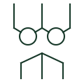
Two phase-to-phase VTs connected in V to provide all three line voltages without a neutral reference.
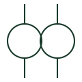
A transformer providing a voltage signal for metering or protection.
Elora Grid helps electrical teams work with drawings, specifications and equipment information. Explore the drafting workflow or join the early-access waitlist.