BESS cabinet
Battery storage cabinet
A generic storage-equipment envelope linked to the selected battery system.
GA objects
In plain English
A passive balancer removes some energy from selected cells through a dissipative path.
A balancing circuit can use a resistor to reduce the charge of a selected cell relative to others.
Draw the balancing branch beside the cell that it can discharge. Passive balancing deliberately turns some stored energy into heat to reduce a selected cell’s charge relative to others. A conceptual diagram should therefore show a dissipative branch, rather than arrows moving energy into a neighbouring cell.
It is dissipated, commonly in a resistive path. This differs from active balancing, which uses a conversion circuit to transfer energy between selected parts of the battery.
Read the source: Battery monitors and balancers
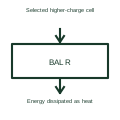
Passive balancing dissipates energy; it does not transfer that energy to another cell.
These public references support the explanation and provide further detail. Their graphics and downloadable files remain with their publishers.
Battery monitors and balancers: public technical context for the named function. Product and compliance details remain with the publisher.
This illustration was authored independently by Elora Grid to explain the concept. It is not reproduced from a customer drawing, an official standard graphic or a manufacturer CAD file. Its correspondence to an exact IEC or IEEE symbol identifier has not been certified.
SVG and DXF downloads contain this original artwork. DXF uses unscaled drawing units; a GA envelope supplies no product dimensions, clearances or fabrication information. Original artwork is available under CC BY 4.0. Third-party references retain their own terms.
A generic storage-equipment envelope linked to the selected battery system.
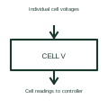
A cell voltage monitor measures individual cells within a series-connected battery.
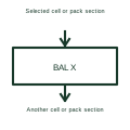
An active balancer transfers energy between selected parts of a battery system.
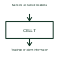
A cell temperature monitor reads sensors located at specified points in a battery assembly.
Elora Grid helps electrical teams work with drawings, specifications and equipment information. Explore the drafting workflow or join the early-access waitlist.