PV INV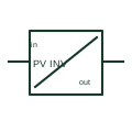
Photovoltaic inverter
A photovoltaic inverter converts a documented PV DC input into an AC output and provides the selected PV control functions.
SLD / Schematic
In plain English
A solar power optimiser uses conversion and control at a selected module or input level.
A module-level optimiser can adjust its operating point within the chosen solar architecture.
Locate the optimiser between its selected solar input and downstream DC arrangement. It uses conversion and control near the module or input it serves. Show the downstream inverter as a separate function unless the selected equipment documentation explicitly combines the roles.
An optimiser is generally a DC-side conversion and control function. The equipment that creates the final AC interface must be identified separately for the selected system.
Read the source: Solar power optimiser architecture
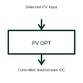
An optimiser is not necessarily the equipment producing the final AC connection.
These public references support the explanation and provide further detail. Their graphics and downloadable files remain with their publishers.
Solar power optimiser architecture: public technical context for the named function. Product and compliance details remain with the publisher.
This illustration was authored independently by Elora Grid to explain the concept. It is not reproduced from a customer drawing, an official standard graphic or a manufacturer CAD file. Its correspondence to an exact IEC or IEEE symbol identifier has not been certified.
SVG and DXF downloads contain this original artwork. DXF uses unscaled drawing units; a GA envelope supplies no product dimensions, clearances or fabrication information. Original artwork is available under CC BY 4.0. Third-party references retain their own terms.
A photovoltaic inverter converts a documented PV DC input into an AC output and provides the selected PV control functions.
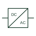
An identified interface converting electrical power between documented circuit forms.

An identified electrical connection point linking schematic and wiring information.
Elora Grid helps electrical teams work with drawings, specifications and equipment information. Explore the drafting workflow or join the early-access waitlist.