PV MOD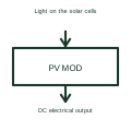
Photovoltaic module
A photovoltaic module converts light into DC electrical power.
Schematic
A small inverter attached to one or two PV modules, converting to AC at the module and paralleling on an AC trunk cable.
In plain English
A microinverter converts the output of one, two or four PV modules to AC right at the array. Each unit has its own maximum power point tracker, so shading on one module does not drag down the rest, and the array wiring carries AC at network voltage instead of high-voltage DC.
Drawings show a small inverter block attached to each module symbol, with AC outputs daisy-chained along a trunk cable to an AC isolator and a dedicated circuit breaker in the switchboard. The number of units per branch circuit is limited by the trunk cable and breaker rating and should be noted.
The symbol does not state the gateway or communication method, nor how many microinverters a branch can carry. Ambient temperature on the roof also affects output, which is not shown on the drawing.
A small inverter attached to one or two PV modules, converting to AC at the module and paralleling on an AC trunk cable. A microinverter converts at module level to AC; a power optimiser stays on the DC side and still needs a string inverter.
Read the source: Solar power optimiser architecture · Photovoltaic technology and inverter functions
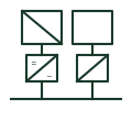
A microinverter converts the output of one, two or four PV modules to AC right at the array. Each unit has its own maximum power point tracker, so shading on one module does not drag down the rest, and the array wiring carries AC at network voltage instead of high-voltage DC.
Drawings show a small inverter block attached to each module symbol, with AC outputs daisy-chained along a trunk cable to an AC isolator and a dedicated circuit breaker in the switchboard. The number of units per branch circuit is limited by the trunk cable and breaker rating and should be noted.
The symbol does not state the gateway or communication method, nor how many microinverters a branch can carry. Ambient temperature on the roof also affects output, which is not shown on the drawing.
A microinverter converts at module level to AC; a power optimiser stays on the DC side and still needs a string inverter.
These public references support the explanation and provide further detail. Their graphics and downloadable files remain with their publishers.
Public module-level power electronics context.
Public photovoltaic inverter function context.
This illustration was authored independently by Elora Grid to explain the concept. It is not reproduced from a customer drawing, an official standard graphic or a manufacturer CAD file. Its correspondence to an exact IEC or IEEE symbol identifier has not been certified.
SVG and DXF downloads contain this original artwork. DXF uses unscaled drawing units; a GA envelope supplies no product dimensions, clearances or fabrication information. Original artwork is available under CC BY 4.0. Third-party references retain their own terms.
A photovoltaic module converts light into DC electrical power.
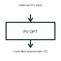
A solar power optimiser uses conversion and control at a selected module or input level.
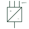
A solar inverter connecting a small number of PV strings directly, each group tracked by its own MPPT input.
Elora Grid helps electrical teams work with drawings, specifications and equipment information. Explore the drafting workflow or join the early-access waitlist.