RC
Rogowski coil current sensor
Air-cored coil around a conductor whose output voltage is proportional to the rate of change of current.
SLD / Schematic
Low-power voltage sensor using a resistive divider to give a small voltage signal proportional to primary voltage.
In plain English
A resistive voltage divider sensor is a low-power instrument transformer in which a high-value resistor chain steps the primary voltage down to a small signal. It has no iron core, so it does not cause ferroresonance, and one sensor can cover a wide range of primary voltages.
The output is a low-energy signal that must go to an input designed for it, and the cable between sensor and relay is part of the measurement. The symbol does not show the division ratio, correction factors or connector type, which must match the relay configuration.
Confirm the relay input is configured for the sensor ratio. Keep the supplied sensor cable unless the manufacturer allows changes. A resistive divider sensor gives a low-level signal; a conventional VT gives a standard secondary voltage capable of supplying burden.
Low-power voltage sensor using a resistive divider to give a small voltage signal proportional to primary voltage. A resistive divider sensor gives a low-level signal; a conventional VT gives a standard secondary voltage capable of supplying burden.
Read the source: Medium-voltage indoor sensors: Rogowski coil and voltage divider low-power instrument transformers · Indoor current and voltage transformers
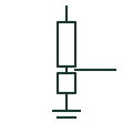
A resistive voltage divider sensor is a low-power instrument transformer in which a high-value resistor chain steps the primary voltage down to a small signal. It has no iron core, so it does not cause ferroresonance, and one sensor can cover a wide range of primary voltages.
The output is a low-energy signal that must go to an input designed for it, and the cable between sensor and relay is part of the measurement. The symbol does not show the division ratio, correction factors or connector type, which must match the relay configuration.
A resistive divider sensor gives a low-level signal; a conventional VT gives a standard secondary voltage capable of supplying burden.
These public references support the explanation and provide further detail. Their graphics and downloadable files remain with their publishers.
Public manufacturer page describing low-power instrument transformers based on Rogowski coils and voltage dividers.
Public manufacturer overview of indoor current and voltage instrument transformers.
This illustration was authored independently by Elora Grid to explain the concept. It is not reproduced from a customer drawing, an official standard graphic or a manufacturer CAD file. Its correspondence to an exact IEC or IEEE symbol identifier has not been certified.
SVG and DXF downloads contain this original artwork. DXF uses unscaled drawing units; a GA envelope supplies no product dimensions, clearances or fabrication information. Original artwork is available under CC BY 4.0. Third-party references retain their own terms.
Air-cored coil around a conductor whose output voltage is proportional to the rate of change of current.

A transformer providing a voltage signal for metering or protection.
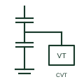
An instrument transformer using a capacitive voltage divider and an electromagnetic unit to supply documented voltage measurement or protection signals.
Elora Grid helps electrical teams work with drawings, specifications and equipment information. Explore the drafting workflow or join the early-access waitlist.