FESS
Flywheel energy storage
A rotating mass coupled to a motor-generator and converter that stores energy kinetically for short, high-power bursts.
SLD
A UPS built around a rotating synchronous machine with kinetic storage, often coupled to a diesel engine for long backup.
In plain English
A rotary UPS uses a synchronous machine running continuously on the critical bus, with stored kinetic energy in a flywheel or induction coupling bridging the gap until a coupled diesel engine starts and takes over. A choke between the utility and the critical bus lets the machine condition the supply and isolate the load from network faults.
Single-line diagrams show the incoming utility feeder, a series choke, the synchronous machine with its kinetic energy module and clutch to the engine, and the critical and sometimes non-critical outputs. A bypass path around the unit is normally drawn.
The machine provides real short-circuit current, unlike a static UPS, which helps downstream protection discriminate. The symbol does not show the ride-through time to engine pickup or the choke impedance, both of which matter for design.
A UPS built around a rotating synchronous machine with kinetic storage, often coupled to a diesel engine for long backup. A rotary UPS uses rotating machines and kinetic storage; a static UPS uses power electronics and a battery.
Read the source: DC UPS, AC UPS and capacitor buffer modules · T-030 liquid-cooled generator set application manual
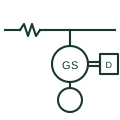
A rotary UPS uses a synchronous machine running continuously on the critical bus, with stored kinetic energy in a flywheel or induction coupling bridging the gap until a coupled diesel engine starts and takes over. A choke between the utility and the critical bus lets the machine condition the supply and isolate the load from network faults.
Single-line diagrams show the incoming utility feeder, a series choke, the synchronous machine with its kinetic energy module and clutch to the engine, and the critical and sometimes non-critical outputs. A bypass path around the unit is normally drawn.
The machine provides real short-circuit current, unlike a static UPS, which helps downstream protection discriminate. The symbol does not show the ride-through time to engine pickup or the choke impedance, both of which matter for design.
A rotary UPS uses rotating machines and kinetic storage; a static UPS uses power electronics and a battery.
These public references support the explanation and provide further detail. Their graphics and downloadable files remain with their publishers.
Public UPS function context.
Public engine-generator application context.
This illustration was authored independently by Elora Grid to explain the concept. It is not reproduced from a customer drawing, an official standard graphic or a manufacturer CAD file. Its correspondence to an exact IEC or IEEE symbol identifier has not been certified.
SVG and DXF downloads contain this original artwork. DXF uses unscaled drawing units; a GA envelope supplies no product dimensions, clearances or fabrication information. Original artwork is available under CC BY 4.0. Third-party references retain their own terms.
A rotating mass coupled to a motor-generator and converter that stores energy kinetically for short, high-power bursts.
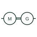
A motor mechanically coupled to a generator, used to isolate, change frequency or convert between AC and DC.
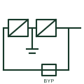
A UPS whose rectifier and inverter carry the load continuously, with the battery on the DC link and a static bypass.
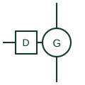
A compression-ignition engine coupled to an alternator, shown as a source on microgrid and standby power single-line diagrams.
Elora Grid helps electrical teams work with drawings, specifications and equipment information. Explore the drafting workflow or join the early-access waitlist.