ATS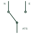
Automatic transfer switch
A mechanically switched changeover device that automatically moves a load from a failed normal source to an alternate source.
SLD / Schematic
A thyristor-based switch that transfers a load between two synchronised sources within a quarter cycle.
In plain English
A static transfer switch uses back-to-back thyristor pairs on each of two sources to move a critical load from one supply to the other in a few milliseconds. It is used in data centres and process plants, typically downstream of two UPS systems, so that a failure in one UPS or its distribution does not interrupt the load.
The single-line diagram shows two incoming feeders, each passing through an anti-parallel thyristor symbol or a solid-state switch box, joining at a common output. Mechanical bypass switches for maintenance are drawn in parallel with the static paths.
Fast transfer only works when the two sources are close in phase. The symbol does not show the synchronisation window, the transfer inhibit logic on downstream faults or how transformer inrush is managed when the load includes transformers.
A thyristor-based switch that transfers a load between two synchronised sources within a quarter cycle. A static transfer switch uses thyristors and transfers in milliseconds; an automatic transfer switch uses mechanical contacts and takes much longer.
Read the source: Transfer switch fundamentals · AutoCAD Electrical: Semiconductor components
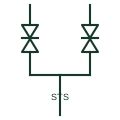
A static transfer switch uses back-to-back thyristor pairs on each of two sources to move a critical load from one supply to the other in a few milliseconds. It is used in data centres and process plants, typically downstream of two UPS systems, so that a failure in one UPS or its distribution does not interrupt the load.
The single-line diagram shows two incoming feeders, each passing through an anti-parallel thyristor symbol or a solid-state switch box, joining at a common output. Mechanical bypass switches for maintenance are drawn in parallel with the static paths.
Fast transfer only works when the two sources are close in phase. The symbol does not show the synchronisation window, the transfer inhibit logic on downstream faults or how transformer inrush is managed when the load includes transformers.
A static transfer switch uses thyristors and transfers in milliseconds; an automatic transfer switch uses mechanical contacts and takes much longer.
These public references support the explanation and provide further detail. Their graphics and downloadable files remain with their publishers.
Public transfer switch fundamentals context.
Public semiconductor symbol family for the thyristor elements.
This illustration was authored independently by Elora Grid to explain the concept. It is not reproduced from a customer drawing, an official standard graphic or a manufacturer CAD file. Its correspondence to an exact IEC or IEEE symbol identifier has not been certified.
SVG and DXF downloads contain this original artwork. DXF uses unscaled drawing units; a GA envelope supplies no product dimensions, clearances or fabrication information. Original artwork is available under CC BY 4.0. Third-party references retain their own terms.
A mechanically switched changeover device that automatically moves a load from a failed normal source to an alternate source.
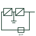
A UPS whose rectifier and inverter carry the load continuously, with the battery on the DC link and a static bypass.
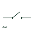
A semiconductor power switch controls a power path electronically.

An equipment assembly connecting a load to the selected supply source.
Elora Grid helps electrical teams work with drawings, specifications and equipment information. Explore the drafting workflow or join the early-access waitlist.