SYNC SCOPE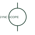
Synchronoscope
A synchronoscope indicates the phase relationship and relative frequency behaviour of two AC sources.
SLD / Schematic
Set of lamps connected between incoming and running phases that brighten and dim with the phase difference during synchronising.
In plain English
Synchronising lamps are connected between corresponding phases of the running system and the incoming machine. As the phase difference changes the lamps brighten and dim, and in the dark-lamp method the breaker is closed when they are dark, showing the voltages are in phase.
Lamps cannot show small residual voltage differences reliably, since a lamp can look dark with a significant voltage across it. They are therefore a backup or visual aid, and the drawing should show a synchroscope or check-synchronising relay for the actual permission to close.
Identify which phases each lamp is connected across. Look for a check-synchronising relay in the closing circuit. Synchronising lamps give a visual indication; a synchroscope shows phase angle and slip direction directly.
Set of lamps connected between incoming and running phases that brighten and dim with the phase difference during synchronising. Synchronising lamps give a visual indication; a synchroscope shows phase angle and slip direction directly.
Read the source: IEC graphical symbols for diagrams · Generator switchgear and paralleling controls
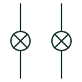
Synchronising lamps are connected between corresponding phases of the running system and the incoming machine. As the phase difference changes the lamps brighten and dim, and in the dark-lamp method the breaker is closed when they are dark, showing the voltages are in phase.
Lamps cannot show small residual voltage differences reliably, since a lamp can look dark with a significant voltage across it. They are therefore a backup or visual aid, and the drawing should show a synchroscope or check-synchronising relay for the actual permission to close.
Synchronising lamps give a visual indication; a synchroscope shows phase angle and slip direction directly.
These public references support the explanation and provide further detail. Their graphics and downloadable files remain with their publishers.
IEC context for graphical symbols used in diagrams; no IEC graphic is reproduced.
Public generator paralleling controls context.
This illustration was authored independently by Elora Grid to explain the concept. It is not reproduced from a customer drawing, an official standard graphic or a manufacturer CAD file. Its correspondence to an exact IEC or IEEE symbol identifier has not been certified.
SVG and DXF downloads contain this original artwork. DXF uses unscaled drawing units; a GA envelope supplies no product dimensions, clearances or fabrication information. Original artwork is available under CC BY 4.0. Third-party references retain their own terms.
A synchronoscope indicates the phase relationship and relative frequency behaviour of two AC sources.
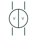
Instrument with two voltage movements in one case, showing running and incoming voltage side by side for synchronising.

Checks documented synchronising conditions before a permitted connection.
Elora Grid helps electrical teams work with drawings, specifications and equipment information. Explore the drafting workflow or join the early-access waitlist.