SCR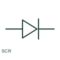
Silicon-controlled rectifier
An SCR is a thyristor with a gate-controlled triggering function in its documented circuit.
Schematic
An AC-to-DC converter using thyristors fired at a controlled angle to set its DC output voltage.
In plain English
A phase-controlled rectifier uses thyristors instead of diodes, so the firing angle sets the average DC output voltage. Six-pulse bridges are widely used for large battery chargers, electrolysers, DC drives and older UPS rectifiers because they are robust and simple to control.
On single-line diagrams it appears as the rectifier box with AC and DC marks plus a thyristor or control additional drawing mark, or as a bridge of thyristor symbols on detailed schematics. A rectifier transformer, line reactor and harmonic filter are often drawn upstream.
Reducing the output voltage by delaying firing also lowers the input power factor, and the converter draws characteristic harmonics at 5th, 7th, 11th and 13th orders. The symbol does not show these effects, which must be assessed with the network harmonic study.
An AC-to-DC converter using thyristors fired at a controlled angle to set its DC output voltage. A phase-controlled rectifier sets voltage by firing angle; an active front-end rectifier uses switched transistors and can run near unity power factor.
Read the source: AutoCAD Electrical: Semiconductor components · IEC graphical symbols for diagrams
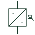
A phase-controlled rectifier uses thyristors instead of diodes, so the firing angle sets the average DC output voltage. Six-pulse bridges are widely used for large battery chargers, electrolysers, DC drives and older UPS rectifiers because they are robust and simple to control.
On single-line diagrams it appears as the rectifier box with AC and DC marks plus a thyristor or control qualifier, or as a bridge of thyristor symbols on detailed schematics. A rectifier transformer, line reactor and harmonic filter are often drawn upstream.
Reducing the output voltage by delaying firing also lowers the input power factor, and the converter draws characteristic harmonics at 5th, 7th, 11th and 13th orders. The symbol does not show these effects, which must be assessed with the network harmonic study.
A phase-controlled rectifier sets voltage by firing angle; an active front-end rectifier uses switched transistors and can run near unity power factor.
These public references support the explanation and provide further detail. Their graphics and downloadable files remain with their publishers.
Public semiconductor symbol family including thyristor forms.
IEC graphical symbol context for converters.
This illustration was authored independently by Elora Grid to explain the concept. It is not reproduced from a customer drawing, an official standard graphic or a manufacturer CAD file. Its correspondence to an exact IEC or IEEE symbol identifier has not been certified.
SVG and DXF downloads contain this original artwork. DXF uses unscaled drawing units; a GA envelope supplies no product dimensions, clearances or fabrication information. Original artwork is available under CC BY 4.0. Third-party references retain their own terms.
An SCR is a thyristor with a gate-controlled triggering function in its documented circuit.
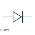
A three-phase bridge rectifier converts a documented three-phase AC input into a DC output.

Two six-pulse bridges fed from star and delta transformer windings 30 degrees apart, cancelling the lowest harmonics.
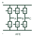
An actively switched AC/DC stage using a documented current-control and DC-link regulation arrangement.
Elora Grid helps electrical teams work with drawings, specifications and equipment information. Explore the drafting workflow or join the early-access waitlist.